Installation
Attaching to an Ethernet device via an AUI cable
The Ethernet device can be a network interface controller, wiring concentrator, or repeater that provides an AUI port. For attaching to such device, an AUI cable of appropriate length is required. The following figure illustrates the connection of the transceiver and an Ethernet device via an AUI cable.
Important:
If the transceiver is attached to an Ethernet repeater, a
Connecting to a fiber optic cable segment
The transceiver has two ST female connectors for hooking up to a duplex fiber optic cable segment. One ST connec- tor is used for transmitting data and the other one is used for receiving data. Two fiber optic cables are required to compose a duplex cable segment between the transceiver and the Fiber Optic port at the other end of the cables.
The Fiber Optic port at the other end of the cables must comply with IEEE 802.3
Interpreting LED Indicators
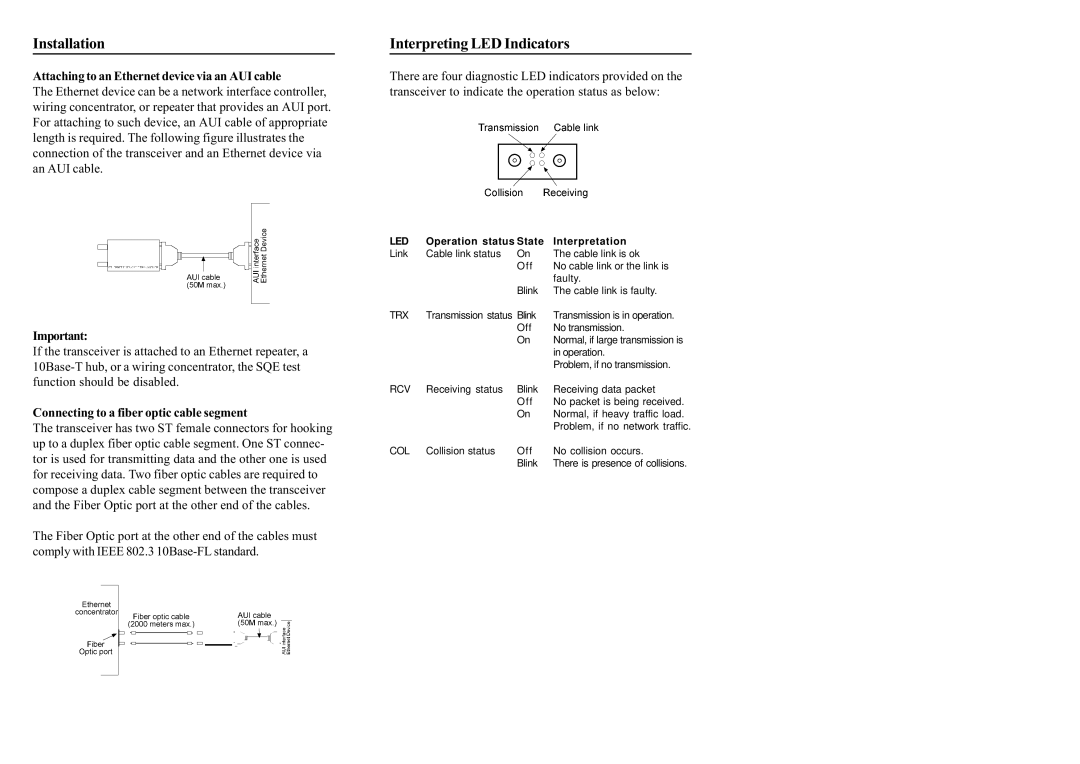
There are four diagnostic LED indicators provided on the transceiver to indicate the operation status as below:
LED | Operation status State | Interpretation | |
Link | Cable link status | On | The cable link is ok |
|
| Off | No cable link or the link is |
|
|
| faulty. |
|
| Blink | The cable link is faulty. |
TRX | Transmission status Blink | Transmission is in operation. | |
|
| Off | No transmission. |
|
| On | Normal, if large transmission is |
|
|
| in operation. |
|
|
| Problem, if no transmission. |
RCV | Receiving status | Blink | Receiving data packet |
|
| Off | No packet is being received. |
|
| On | Normal, if heavy traffic load. |
|
|
| Problem, if no network traffic. |
COL | Collision status | Off | No collision occurs. |
|
| Blink | There is presence of collisions. |