3
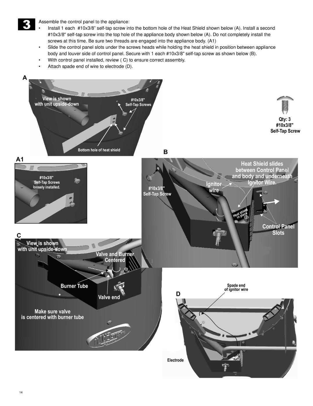
Assemble the control panel to the appliance:
•Install 1 each #10x3/8”
•Slide the control panel slots under the screws heads while holding the heat shield in position between appliance body and louver side of control panel. Secure with 1 each #10x3/8"
•With control panel installed, review ( C) to ensure correct assembly.
•Attach spade end of wire to electrode (D).
A
View is shown | #10x3/8" |
with unit |
Bottom hole of heat shield | B |
|
A1
#10x3/8" |
|
| |
loosely installed. | #10x3/8" |
|
C
View is shown
with unit
Valve and Burner
Centered
Ignitor![]() wire
wire
Qty: 3
#10x3/8"
Heat Shield slides
between Control Panel
and body and underneath Wire.
shield Heat place in
Control Panel
Slots
Burner Tube
Valve end
Make sure valve
is centered with burner tube
D
Spade end
of ignitor wire
Electrode
14
