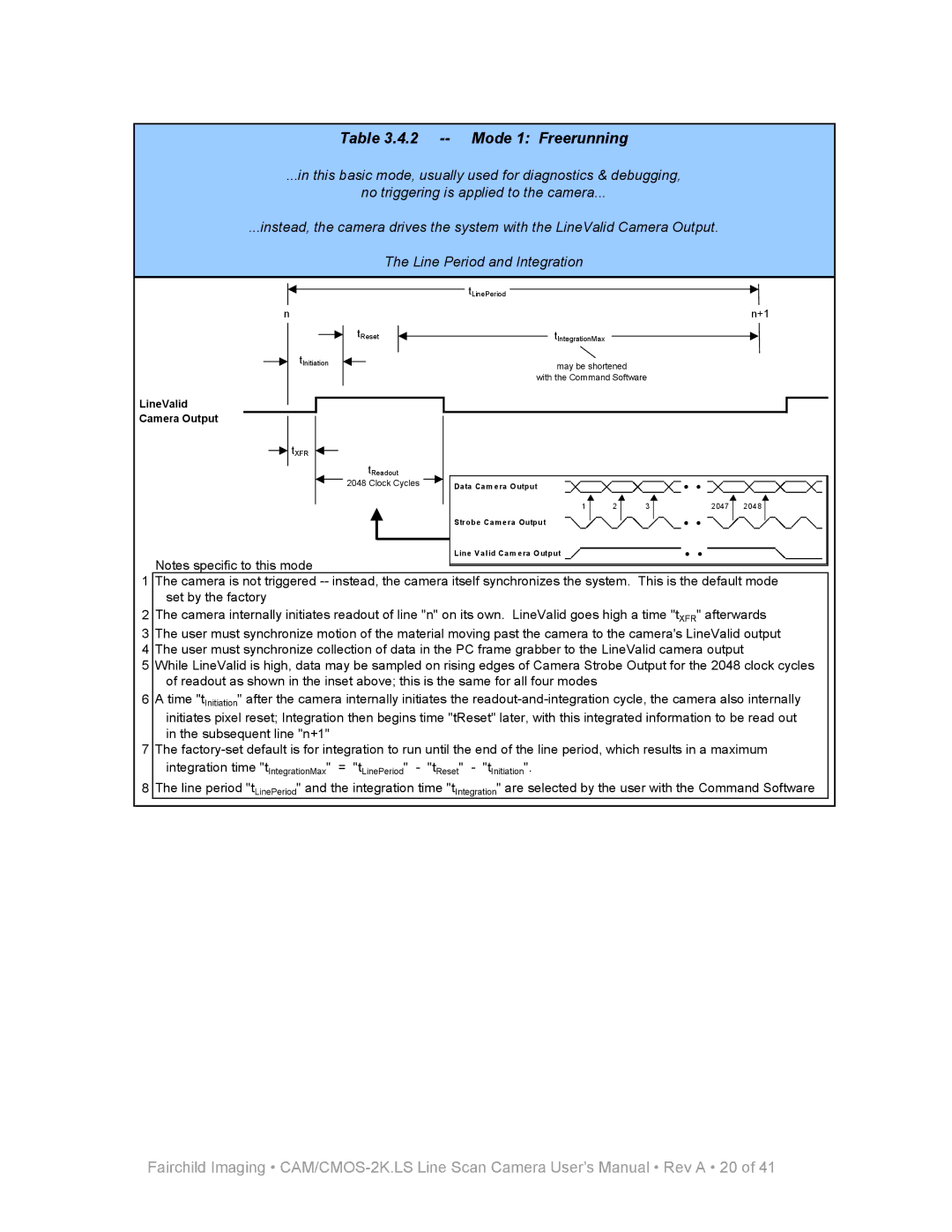
Table 3.4.2 -- Mode 1: Freerunning
...in this basic mode, usually used for diagnostics & debugging,
no triggering is applied to the camera...
...instead, the camera drives the system with the LineValid Camera Output.
|
|
|
|
|
|
|
|
|
|
|
|
| The Line Period and Integration | |||||||||||
|
|
|
|
|
|
|
|
|
|
|
|
|
|
|
|
|
|
|
|
|
|
|
|
|
|
|
|
|
|
|
|
|
|
|
|
|
|
|
|
|
|
|
|
|
|
|
|
|
|
|
|
|
|
|
|
|
|
|
|
|
|
|
|
|
| tLinePeriod |
|
|
|
|
|
|
|
|
|
|
|
|
|
|
|
|
|
|
|
|
|
|
|
|
|
|
|
|
|
|
|
| |
|
|
|
|
|
|
|
|
|
|
|
|
|
|
|
|
|
|
|
|
|
| |||
|
|
|
|
|
|
|
|
|
|
|
|
|
|
|
|
|
|
|
|
|
|
|
|
|
|
| n |
|
|
|
|
|
|
|
|
|
|
| n+1 |
| |||||||||
|
|
|
|
|
|
|
|
|
|
|
|
|
|
|
|
|
|
|
|
|
|
|
| |
|
|
|
|
|
|
|
|
|
|
|
|
|
|
|
|
|
|
|
|
|
|
|
|
|
|
|
|
|
|
|
|
|
|
|
| tReset |
|
|
|
|
|
| tIntegrationMax |
|
|
|
|
| |
|
|
|
|
|
|
|
|
|
|
|
|
|
|
|
|
|
|
|
|
|
| |||
|
|
|
|
|
|
|
|
|
|
|
|
|
|
|
|
|
|
|
| |||||
|
|
|
|
|
|
|
|
|
|
|
|
|
|
|
|
|
|
|
|
|
|
|
| |
|
|
|
|
|
|
|
|
|
|
|
|
|
|
|
|
|
|
|
|
|
|
| ||
|
|
|
|
| tInitiation |
|
|
|
|
|
|
|
|
|
|
|
|
|
|
|
|
|
| |
|
|
|
|
|
|
|
|
|
|
|
|
|
|
|
|
| may be shortened |
|
|
|
| |||
|
|
|
|
|
|
|
|
|
|
|
|
|
|
|
| |||||||||
|
|
|
|
|
|
|
|
|
|
|
|
|
|
|
|
|
|
|
| |||||
|
|
|
|
|
|
|
|
|
|
|
|
|
|
|
|
|
| with the Command Software |
| |||||
|
|
|
|
|
|
|
|
|
|
|
|
|
|
|
|
|
|
|
|
|
|
|
|
|
LineValid
Camera Output
tXFR
tReadout
2048 Clock Cycles | Data Cam era Output |
|
1 | 2 | 3 | 2047 | 2048 |
Strobe Camera Output
Line Valid Cam era Output
Notes specific to this mode
1The camera is not triggered
2The camera internally initiates readout of line "n" on its own. LineValid goes high a time "tXFR" afterwards
3The user must synchronize motion of the material moving past the camera to the camera's LineValid output
4The user must synchronize collection of data in the PC frame grabber to the LineValid camera output
5While LineValid is high, data may be sampled on rising edges of Camera Strobe Output for the 2048 clock cycles of readout as shown in the inset above; this is the same for all four modes
6A time "tInitiation" after the camera internally initiates the
7The
integration time "tIntegrationMax" = "tLinePeriod" - "tReset" - "tInitiation".
8 The line period "tLinePeriod" and the integration time "tIntegration" are selected by the user with the Command Software
Fairchild Imaging •