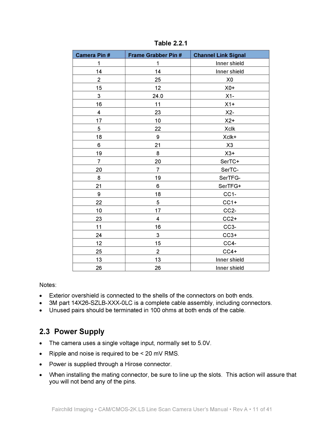
Table 2.2.1
Camera Pin # | Frame Grabber Pin # | Channel Link Signal |
1 | 1 | Inner shield |
14 | 14 | Inner shield |
2 | 25 | X0 |
15 | 12 | X0+ |
3 | 24.0 | X1- |
16 | 11 | X1+ |
4 | 23 | X2- |
17 | 10 | X2+ |
5 | 22 | Xclk |
18 | 9 | Xclk+ |
6 | 21 | X3 |
19 | 8 | X3+ |
7 | 20 | SerTC+ |
20 | 7 | SerTC- |
8 | 19 | SerTFG- |
21 | 6 | SerTFG+ |
9 | 18 | CC1- |
22 | 5 | CC1+ |
10 | 17 | CC2- |
23 | 4 | CC2+ |
11 | 16 | CC3- |
24 | 3 | CC3+ |
12 | 15 | CC4- |
25 | 2 | CC4+ |
13 | 13 | Inner shield |
26 | 26 | Inner shield |
Notes:
•Exterior overshield is connected to the shells of the connectors on both ends.
•3M part
•Unused pairs should be terminated in 100 ohms at both ends of the cable.
2.3 Power Supply
•The camera uses a single voltage input, normally set to 5.0V.
•Ripple and noise is required to be < 20 mV RMS.
•Power is supplied through a Hirose connector.
•When installing the mating connector, be sure to line up the slots. This action will assure that you will not bend any of the pins.
Fairchild Imaging •
