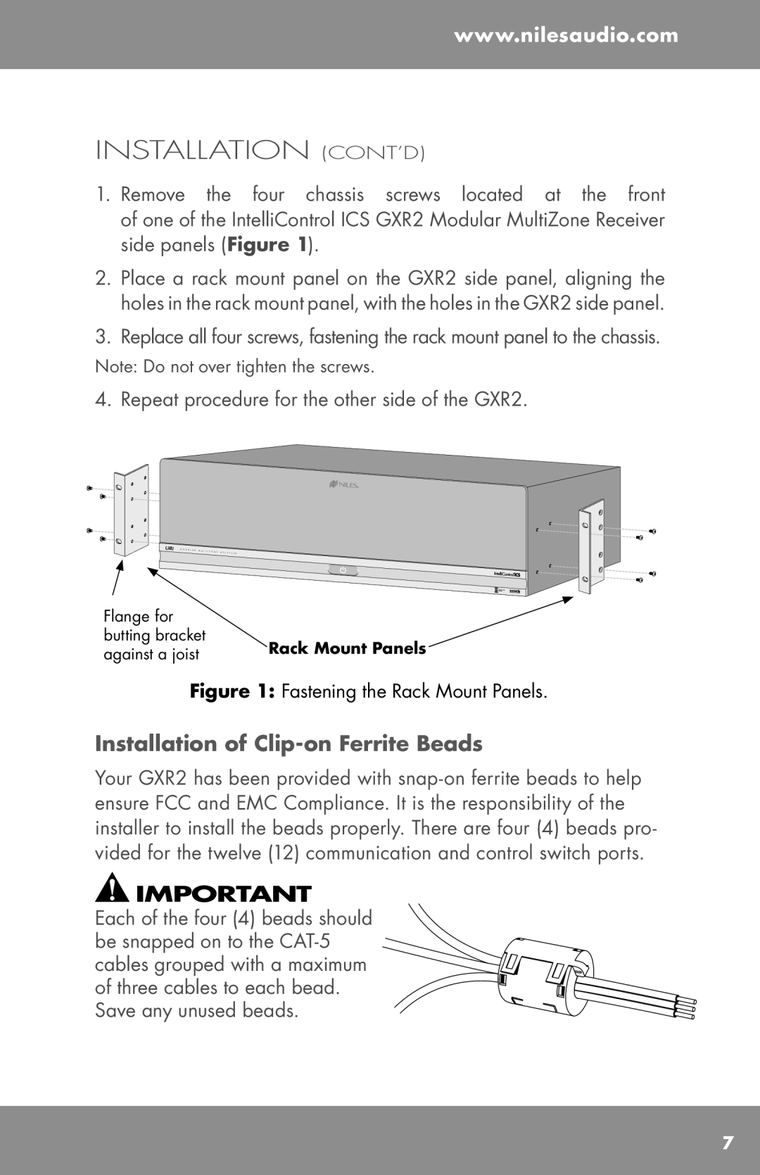
GXR2 specifications
The Niles Audio GXR2 is a cutting-edge audio distribution system designed for multi-room audio applications, providing an impressive balance of high-quality sound and user-friendly versatility. This powerful component is ideal for both residential and commercial installations, making it a popular choice among homeowners, installers, and audio enthusiasts alike.One of the main features of the GXR2 is its ability to distribute high-fidelity audio to up to six distinct zones. Each zone can be independently controlled, allowing users to enjoy different music or audio sources in different rooms simultaneously. This feature is particularly beneficial in larger homes or commercial establishments where customized audio experiences are desired.
The GXR2 is equipped with advanced technology that ensures optimal sound quality. With a built-in digital signal processing (DSP) engine, the unit allows users to tailor audio output according to their unique preferences and the specific acoustic characteristics of each zone. This includes options for equalization, volume leveling, and bass management, guaranteeing a premium listening experience regardless of where listeners are located within the coverage area.
Another noteworthy characteristic of the Niles Audio GXR2 is its compatibility with a variety of media sources. Users can enjoy audio from traditional sources, such as CD players and tuners, alongside modern streaming services and digital music libraries. The device supports both wired and wireless connections, including Bluetooth and Wi-Fi, enabling easy integration with smartphones, tablets, and computers.
In terms of control, the GXR2 offers various options tailored to different user preferences. It supports web-based control, allowing users to manage their audio system from any device with internet connectivity. Additionally, it is compatible with third-party control systems, enabling seamless integration into existing home automation setups.
Furthermore, the GXR2's design seamlessly blends aesthetics with functionality. Its sleek, contemporary look allows for elegant installation in any environment, while its robust build ensures durability and reliability over time.
With the Niles Audio GXR2, users can experience the pinnacle of multi-room audio technology, characterized by customizable sound distribution, versatile connectivity options, and effortless control. This system is an excellent choice for those looking to elevate their audio experience to a whole new level.

