INSTALLATION (CONTINUED)
STEP 6 – MOUNTING THE CONNECTION HUB
Make sure that your system tested OK before proceeding.
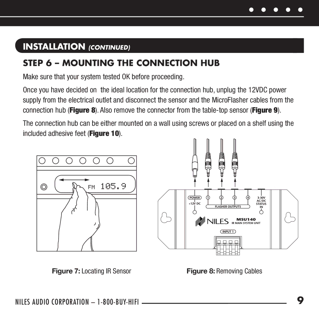
Once you have decided on the ideal location for the connection hub, unplug the 12VDC power supply from the electrical outlet and disconnect the sensor and the MicroFlasher cables from the connection hub (Figure 8). Also remove the connector from the
The connection hub can be either mounted on a wall using screws or placed on a shelf using the included adhesive feet (Figure 10).
Figure 7: Locating IR Sensor | Figure 8: Removing Cables |
NILES AUDIO CORPORATION – | 9 |