INSTALLATION (CONTINUED)
STEP 4 – CONNECTING THE 12VDC IN-LINE POWER SUPPLY AND MICROFLASHERS®
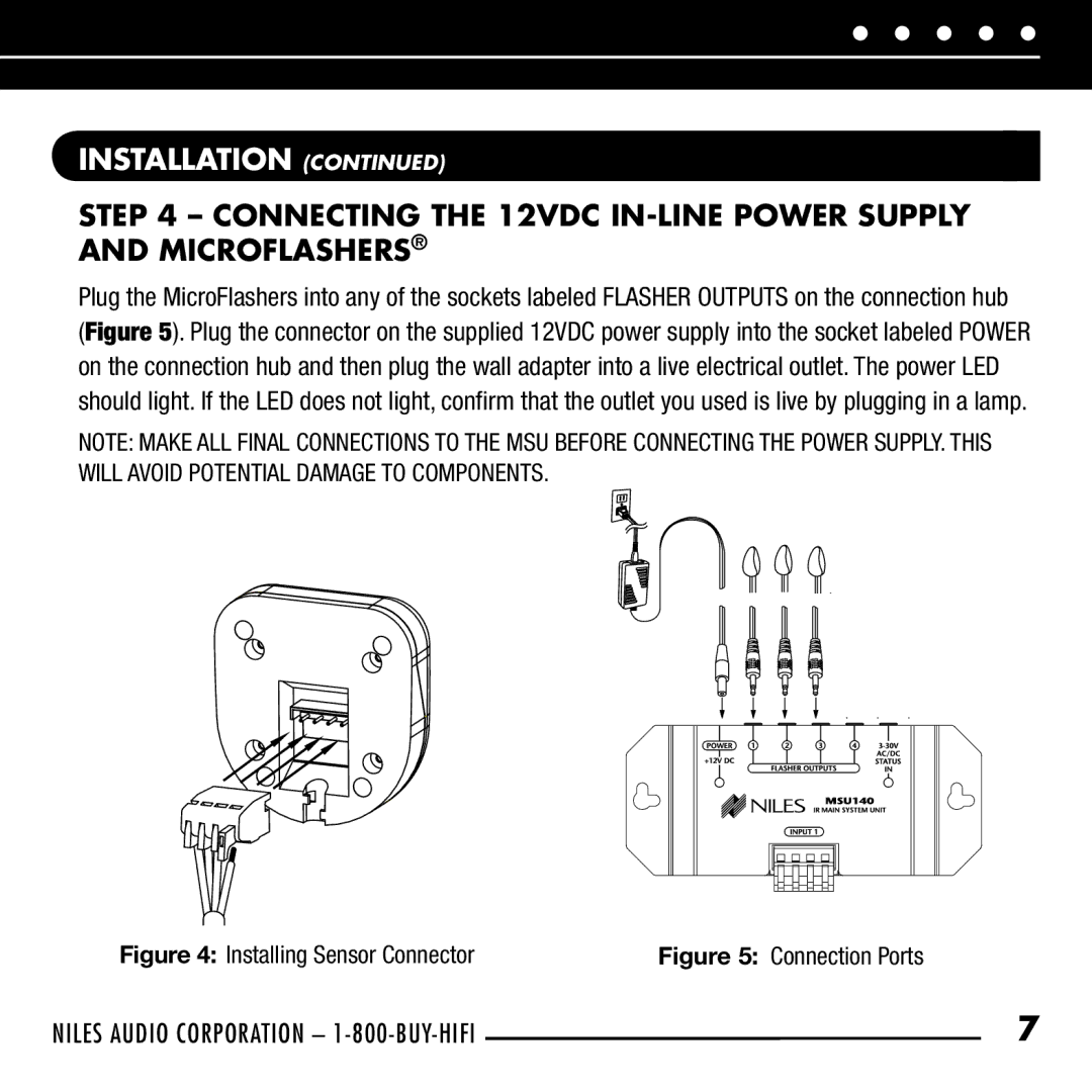
Plug the MicroFlashers into any of the sockets labeled FLASHER OUTPUTS on the connection hub
(Figure 5). Plug the connector on the supplied 12VDC power supply into the socket labeled POWER on the connection hub and then plug the wall adapter into a live electrical outlet. The power LED should light. If the LED does not light, confirm that the outlet you used is live by plugging in a lamp.
NOTE: MAKE ALL FINAL CONNECTIONS TO THE MSU BEFORE CONNECTING THE POWER SUPPLY. THIS WILL AVOID POTENTIAL DAMAGE TO COMPONENTS.INSTALLATION CONTINU
Figure 4: Installing Sensor Connector | Figure 5: Connection Ports |
NILES AUDIO CORPORATION – | 7 |