INSTALLATION (CONTINUED)
STEP 2 – CONNECTING THE SENSOR CABLE TO THE CONNECTION HUB
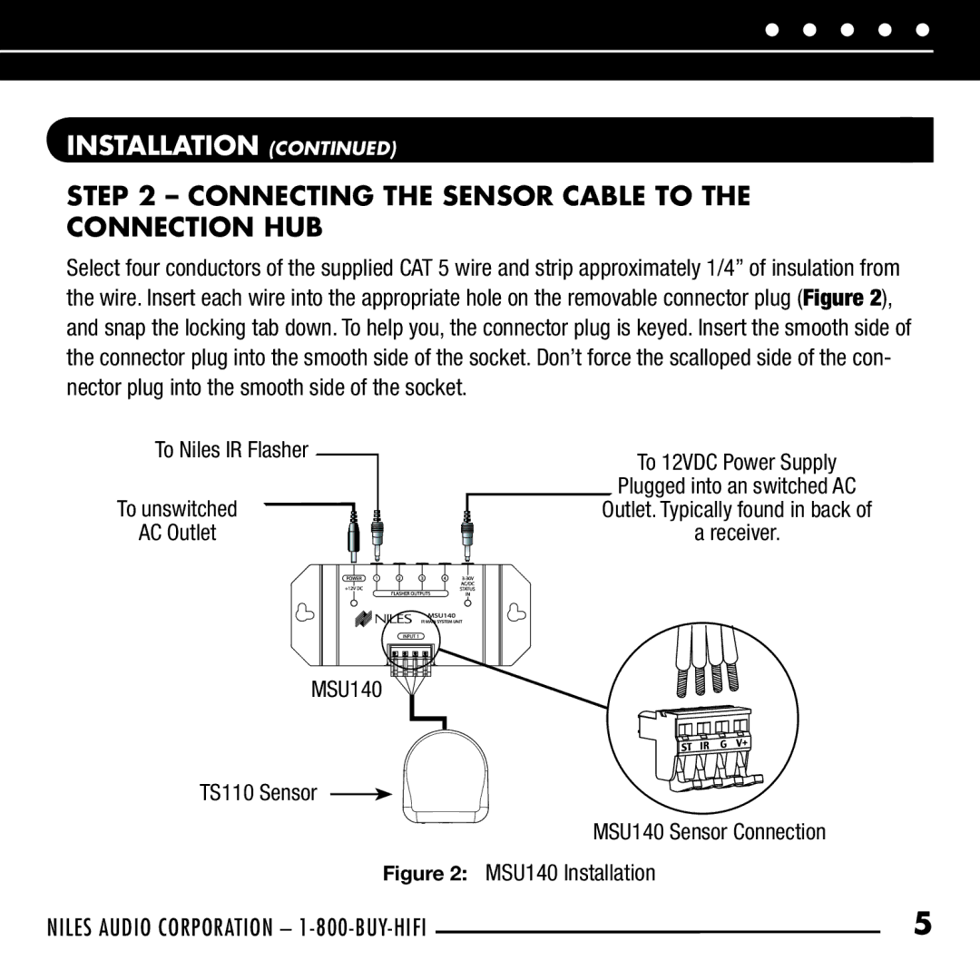
Select four conductors of the supplied CAT 5 wire and strip approximately 1/4” of insulation from the wire. Insert each wire into the appropriate hole on the removable connector plug (Figure 2), and snap the locking tab down. To help you, the connector plug is keyed. Insert the smooth side of the connector plug into the smooth side of the socket. Don’t force the scalloped side of the con- nector plug into the smooth side of the socket.
To Niles IR Flasher
To unswitched
AC Outlet
MSU140
TS110 Sensor
To 12VDC Power Supply
Plugged into an switched AC
Outlet. Typically found in back of
a receiver.
MSU140 Sensor Connection
Figure 2: MSU140 Installation
NILES AUDIO CORPORATION – | 5 |