1Power LED
This LED lights up when the unit is powered on.
2Power Switch
Turn the unit on or off.
3Level Control for Channels 1 & 2
Adjust the output signal level of respective channel.
4Clip LED
When the LED lights up, it means the output level of signal is too high and it is time to reduce the signal level until clip LED turns off.
5Limit LED
While the unit is limiting the output signal, the LED lights up.
6Signal LED
When there are signals present in this unit, the LED lights up, or it will be off.
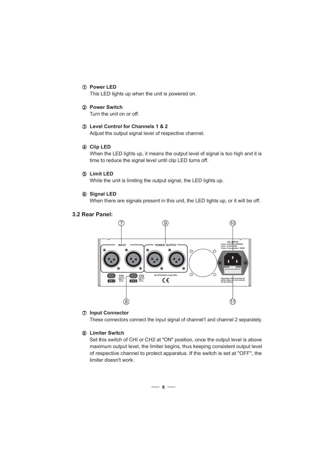
3.2 Rear Panel:
|
| 7 |
|
|
|
|
| 9 |
|
|
| INPUT |
|
|
| POWER OUTPUT |
| ||
2 | 1 |
| 2 | 1 |
| 2 | 1 | 2 | 1 |
|
| CH1 |
|
| CH2 | 4 | SPEAKER LOAD MIN. |
| |
|
|
|
|
|
|
|
| ||
|
| LIMITER |
|
| LIMITER |
|
|
|
|
CH.1 | OFF | CH.2 | OFF |
|
|
|
| ||
ON | ON |
|
|
|
| ||||
10
AC INPUT
Input: ![]() 50/60Hz
50/60Hz
Fuse: T6.3AL 250V
Power Consumption: 450W
Use only with a 250V fuse
Apparaten skall anslutas till jordat uttag nar den ansluts till ett natverk
8 | 11 |
7Input Connector
These connectors connect the input signal of channel1 and channel 2 separately.
8Limiter Switch
Set this switch of CHI or CH2 at "ON" position, once the output level is above maximum output level, the limiter begins, thus keeping consistent output level of respective channel to protect apparatus. If the switch is set at "OFF", the limiter doesn't work.
6
