1. INTRODUCTION
With ![]() LTO-Q
LTO-Q![]() LTO-Q
LTO-Q![]() LTO-Q
LTO-Q
2.FEATURES
![]() Mountable in one standard rack unit 19"
Mountable in one standard rack unit 19"
![]() 1/4" TRS type jack and balanced XLR connectors available
1/4" TRS type jack and balanced XLR connectors available
![]() Led Meter (12 LED) to read input and output
Led Meter (12 LED) to read input and output
![]() Low cut and high cut filters available to cancel unwanted frequencies
Low cut and high cut filters available to cancel unwanted frequencies
![]() Bypass function to connect automatically input and output
Bypass function to connect automatically input and output
![]() Optimum transparency of the audio signal and minimum phase shift insured by the parallel architecture of the filters
Optimum transparency of the audio signal and minimum phase shift insured by the parallel architecture of the filters
![]()
![]() Constant Q principle combination
Constant Q principle combination
![]() 5 bands of equalisation fully parametric (gain, frequency, Q) for studio and live applications
5 bands of equalisation fully parametric (gain, frequency, Q) for studio and live applications
![]() The frequency range of the single 5 bands is overlapping. This will allow extreme boost or attenuation
The frequency range of the single 5 bands is overlapping. This will allow extreme boost or attenuation
3.ELEMENT CONTROLS
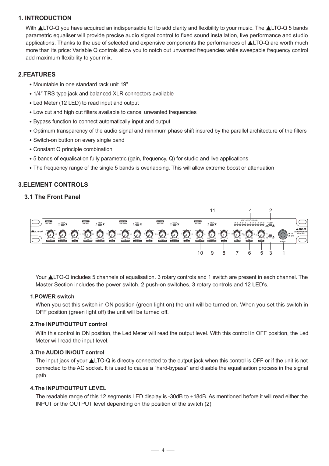
3.1 The Front Panel
|
|
|
|
|
|
|
|
| 11 | 4 | 2 | |||
BAND 1 |
| BAND 2 |
| BAND 3 |
| BAND 4 |
| BAND 5 |
|
| INPUT / OUTPUT | LEVEL (dB) |
|
|
|
|
|
|
|
|
|
|
|
| |||||
20Hz - 400Hz | IN IN / OUT OUT | 60Hz - 1KHz | IN IN / OUT OUT | 150Hz - 2.5KHz | IN IN / OUT OUT | 500Hz - 8KHz | IN IN / OUT OUT | 1KHz - 20KHz | IN IN / OUT OUT | I / O METER | ||||
|
|
|
|
|
|
|
|
|
|
|
|
|
|
|
|
|
|
|
|
|
|
|
|
|
|
| OUTPUT | INPUT |
| |
| 110 | 1.2 | 0 |
| 260 | 1.2 | 0 |
| 720 | 1.2 |
| 0 |
| 2.3 | 1.2 | 0 |
| 5.1 | 1.2 | 0 |
| 75 |
| 10 |
|
| 0 |
|
| Q |
LTOR | 45 | 150 | +5 | 120 | 360 | +5 | 350 | 1K | +5 | 1.0 |
| 3.1 | +5 | 2.2 | 7.0 | +5 | 50 | 110 | 7 | 15 | +5 |
|
| |||||||
| 30 | 250 | +10 | 70 | 600 |
| +10 200 | 1.6K | +10 | 0.6 |
| 4.8 | +10 | 1.3 | 12 | +10 | 25 | 200 |
|
| 22 | +10 |
| ON | EQUALIZER | |||||
|
|
|
|
| AUDIO |
| ||||||||||||||||||||||||
|
|
|
|
|
|
|
|
|
|
|
|
|
|
|
|
|
|
|
|
|
|
| 3.5 |
|
|
|
| OFF |
| |
|
|
|
|
|
|
|
|
|
|
|
|
|
|
|
|
|
|
|
|
|
|
|
|
|
|
|
|
|
| |
20 | 400 | 0.03 | 1.6 | +15 | 60 | 1K | 0.03 | 1.6 | +15 | 150 | 2.5K | 0.03 | 1.6 | +15 | 0.5 | 8.0 | 0.03 | 1.6 | +15 | 1.0 | 20 | 0.03 | 1.6 | +15 | 10 | 400 | 2.5 | 30 | +15 IN | OUT | ||||||
| Hz | OCTAVE |
|
| dB |
| Hz | OCTAVE |
|
| dB |
| Hz | OCTAVE |
|
| dB |
| KHz | OCTAVE |
|
| dB |
| KHz | OCTAVE |
|
| dB |
| Hz |
| KHz |
| dB |
|
FREQUENCY | BANDWIDTH |
| LEVEL | FREQUENCY | BANDWIDTH |
| LEVEL | FREQUENCY | BANDWIDTH |
| LEVEL | FREQUENCY | BANDWIDTH |
| LEVEL | FREQUENCY | BANDWIDTH |
| LEVEL | LOW CUT | HIGH CUT |
| INPUT | POWER | ||||||||||||
|
|
|
|
|
|
|
|
|
|
|
|
|
|
|
|
|
|
|
|
|
|
|
|
|
|
|
|
|
|
|
|
|
|
|
| |
10 | 9 | 8 | 7 | 6 | 5 | 3 | 1 |
Your ![]() LTO-Q
LTO-Q
1.POWER switch
When you set this switch in ON position (green light on) the unit will be turned on. When you set this switch in OFF position (green light off) the unit will be turned off.
2.The INPUT/OUTPUT control
With this control in ON position, the Led Meter will read the output level. With this control in OFF position, the Led Meter will read the input level.
3.The AUDIO IN/OUT control
The input jack of your ![]() LTO-Q
LTO-Q
4.The INPUT/OUTPUT LEVEL
The readable range of this 12 segments LED display is
4