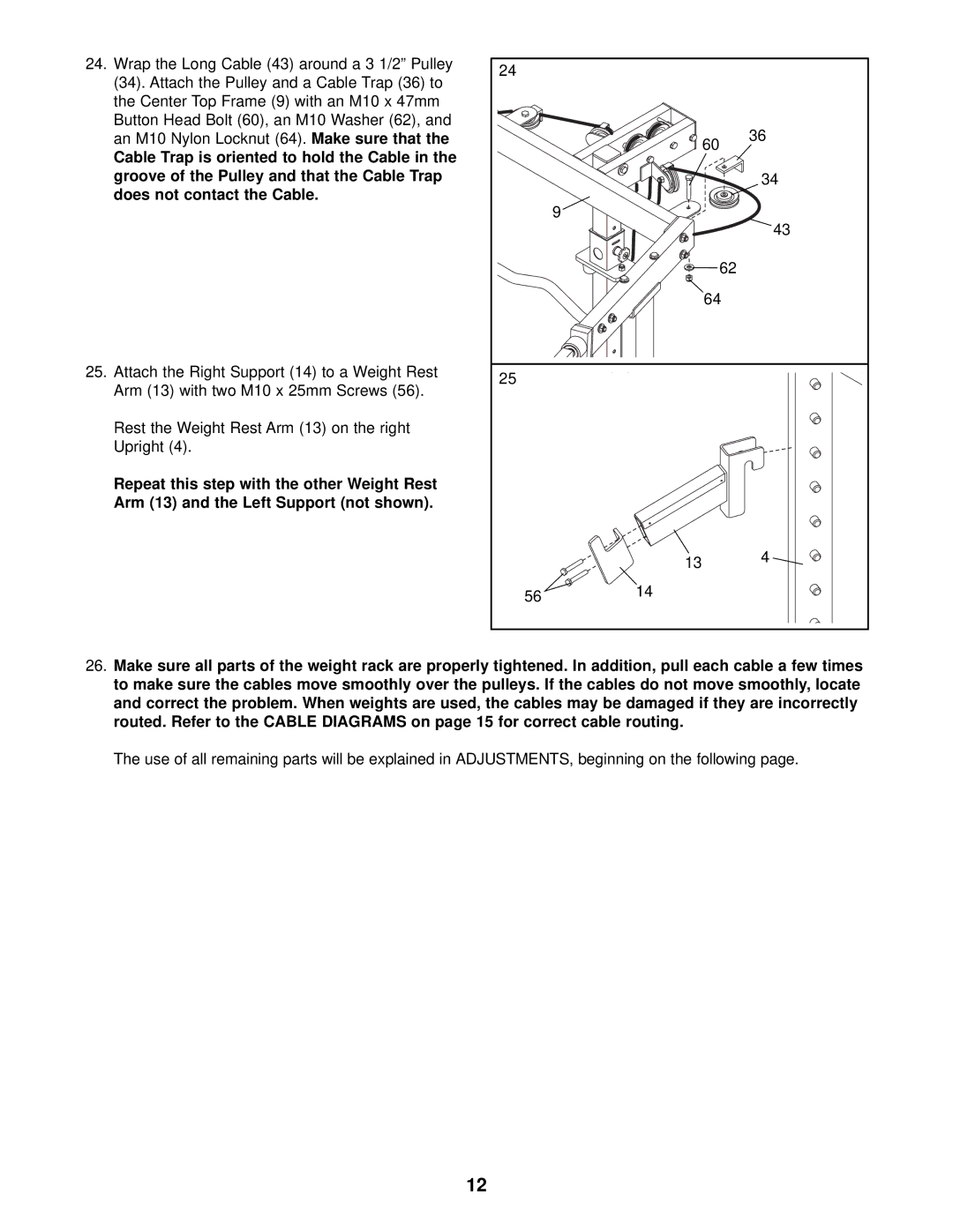
24. Wrap the Long Cable (43) around a 3 1/2” Pulley | 24 |
|
|
|
(34). Attach the Pulley and a Cable Trap (36) to |
|
|
| |
|
|
|
| |
the Center Top Frame (9) with an M10 x 47mm |
|
|
|
|
Button Head Bolt (60), an M10 Washer (62), and |
|
|
| 36 |
an M10 Nylon Locknut (64). Make sure that the |
|
| 60 | |
Cable Trap is oriented to hold the Cable in the |
|
|
| |
|
|
|
| |
groove of the Pulley and that the Cable Trap |
|
|
| 34 |
does not contact the Cable. |
| 9 |
|
|
|
|
| 43 | |
|
|
|
| |
|
|
| 62 |
|
|
|
| 64 |
|
25. Attach the Right Support (14) to a Weight Rest | 25 |
|
|
|
Arm (13) with two M10 x 25mm Screws (56). |
|
|
| |
|
|
|
| |
Rest the Weight Rest Arm (13) on the right |
|
|
|
|
Upright (4). |
|
|
|
|
Repeat this step with the other Weight Rest |
|
|
|
|
Arm (13) and the Left Support (not shown). |
|
|
|
|
|
| 13 |
| 4 |
|
|
|
| |
| 56 | 14 |
|
|
|
|
|
|
26.Make sure all parts of the weight rack are properly tightened. In addition, pull each cable a few times to make sure the cables move smoothly over the pulleys. If the cables do not move smoothly, locate and correct the problem. When weights are used, the cables may be damaged if they are incorrectly routed. Refer to the CABLE DIAGRAMS on page 15 for correct cable routing.
The use of all remaining parts will be explained in ADJUSTMENTS, beginning on the following page.
12
