INSTALLATION
RECEIVING & UNPACKING EQUIPMENT
1.Check packing slip to ensure ALL material has been delivered.
2.All material shortages are to be reported to NORTEC within 48 hours from receipt of goods. NORTEC assumes no responsibility for any material shortages beyond this period.
3.Inspect shipping boxes for damage and note on shipping waybill accordingly.
4.After unpacking, inspect equipment for damage and if damage is found, notify the shipper promptly.
5.All NORTEC products are shipped on an F.O.B. factory basis. Any and all damage, breakage or loss claims are to be made directly to the shipping company.
PRE-INSTALLATION CHECKPOINT
1.Ensure that available voltage and phase corresponds with humidifier voltage and phase as indicated on humidifier’s nameplate label.
2.Ensure that the dedicated external disconnect switch is of sufficient size to handle the rated amps as indicated on the nameplate label. Refer to local codes.
3.Report any discrepancy immediately.
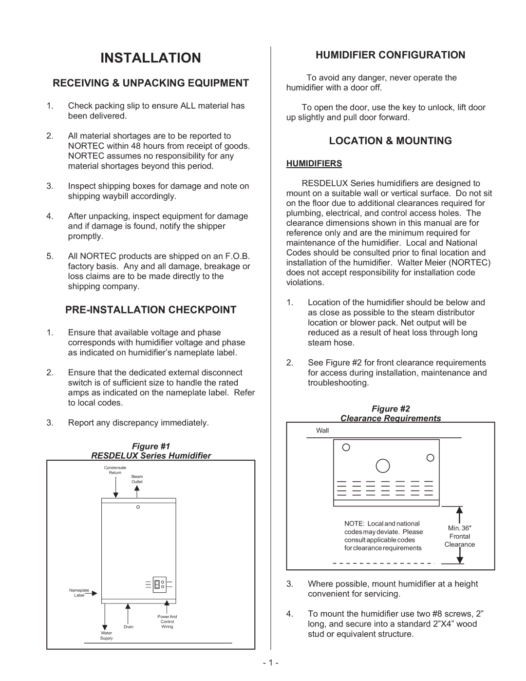
Figure #1
RESDELUX Series Humidifier
Condensate
Return
Steam
Outlet
Nameplate
Label
PowerAnd
Control
DrainWiring
Water
Supply
HUMIDIFIER CONFIGURATION
To avoid any danger, never operate the humidifier with a door off.
To open the door, use the key to unlock, lift door up slightly and pull door forward.
LOCATION & MOUNTING
HUMIDIFIERS
RESDELUX Series humidifiers are designed to mount on a suitable wall or vertical surface. Do not sit on the floor due to additional clearances required for plumbing, electrical, and control access holes. The clearance dimensions shown in this manual are for reference only and are the minimum required for maintenance of the humidifier. Local and National Codes should be consulted prior to final location and installation of the humidifier. Walter Meier (NORTEC) does not accept responsibility for installation code violations.
1.Location of the humidifier should be below and as close as possible to the steam distributor location or blower pack. Net output will be reduced as a result of heat loss through long steam hose.
2.See Figure #2 for front clearance requirements for access during installation, maintenance and troubleshooting.
Figure #2
Clearance Requirements
Wall |
| |
NOTE: Local and national | Min. 36" | |
codes may deviate. Please | ||
Frontal | ||
consult applicable codes | ||
Clearance | ||
for clearance requirements | ||
|
3.Where possible, mount humidifier at a height convenient for servicing.
4.To mount the humidifier use two #8 screws, 2” long, and secure into a standard 2”X4” wood stud or equivalent structure.
- 1 -