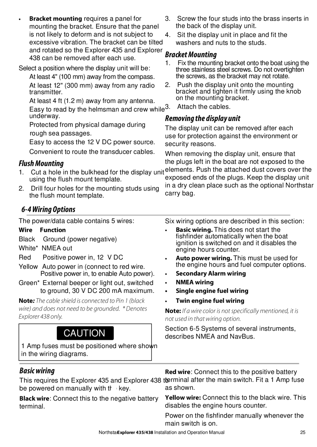
435, 438 specifications
NorthStar Navigation 438,435 is a cutting-edge navigation solution designed to enhance maritime and aerial operations with advanced technology and user-friendly features. This state-of-the-art equipment focuses on delivering precision, reliability, and efficiency, making it an essential tool for professionals in various fields including marine transportation, aviation, and logistics.One of the main features of the NorthStar Navigation 438,435 is its high-accuracy positioning capability. Utilizing multiple GNSS (Global Navigation Satellite System) signals, including GPS, GLONASS, Galileo, and BeiDou, the system can provide a positioning accuracy of up to 10 centimeters in real-time. This ensures that users can navigate confidently in challenging environments, whether at sea or in the air.
The navigation device also boasts robust integration capabilities with other onboard systems. It supports various communication protocols, allowing seamless interfacing with radar, AIS (Automatic Identification System), and autopilot systems. This integrated approach facilitates comprehensive situational awareness, enabling operators to make informed decisions swiftly.
Moreover, the NorthStar Navigation 438,435 features an intuitive user interface designed for ease of use. The touchscreen display provides clear visuals and customizable layouts, allowing users to tailor the information presented to their specific needs. With multiple language support and user-friendly controls, the system caters to diverse operators across different geographic regions.
Another defining characteristic of the NorthStar Navigation 438,435 is its resilience in harsh conditions. Built to withstand severe weather, it meets stringent marine and aviation industry standards for durability and reliability. The system is both waterproof and shock-resistant, ensuring optimal performance even in extreme environments.
In addition to its hardware capabilities, the NorthStar Navigation 438,435 incorporates advanced software features such as real-time route planning and environmental monitoring. Users can analyze weather patterns and potential hazards along their route, optimizing travel time and enhancing safety.
Overall, the NorthStar Navigation 438,435 stands as a reliable, feature-rich navigation solution that harmonizes advanced technology with user-centric design. Its focus on accuracy, integration, ease of use, and durability makes it an indispensable tool for navigating the complexities of modern transportation, ensuring successful missions across diverse maritime and aerial operations.

