|
|
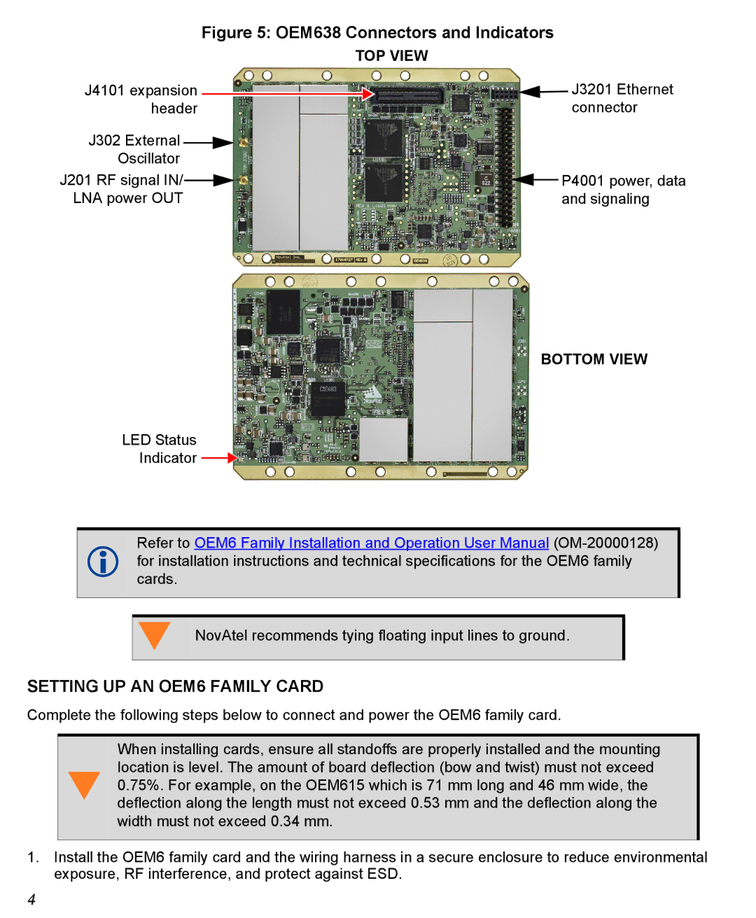
| Figure 5: OEM638 Connectors and Indicators | ||||||
|
|
|
| TOP VIEW | |||||
J4101 expansion |
|
|
|
|
|
| J3201 Ethernet | ||
|
|
|
|
|
| ||||
header |
|
|
|
|
|
| connector | ||
|
|
|
|
|
| ||||
J302 External |
|
|
|
|
|
|
|
|
|
Oscillator |
|
|
|
|
|
|
| ||
J201 RF signal IN/ |
|
|
|
|
|
|
| P4001 power, data | |
|
|
|
|
|
|
| |||
|
|
|
|
|
| ||||
LNA power OUT |
|
|
|
|
|
| and signaling | ||
BOTTOM VIEW
LED Status
Indicator ![]()
![]()
Refer to OEM6 Family Installation and Operation User Manual
forcards.installation instructions and technical specifications for the OEM6 family
NovAtel recommends tying floating input lines to ground.
SETTING UP AN OEM6 FAMILY CARD
Complete the following steps below to connect and power the OEM6 family card.
When installing cards, ensure all standoffs are properly installed and the mounting location is level. The amount of board deflection (bow and twist) must not exceed
0.75%. For example, on the OEM615 which is 71 mm long and 46 mm wide, the deflection along the length must not exceed 0.53 mm and the deflection along the width must not exceed 0.34 mm.
1.Install the OEM6 family card and the wiring harness in a secure enclosure to reduce environmental exposure, RF interference, and protect against ESD.
4
