INSTALLATION & OPERATING INSTRUCTIONS
READ & SAVE THESE INSTRUCTIONS!
Two-Note Wireless Chime
MODEL: LA-205WH
MOUNTING THE PUSHBUTTON TRANSMITTER
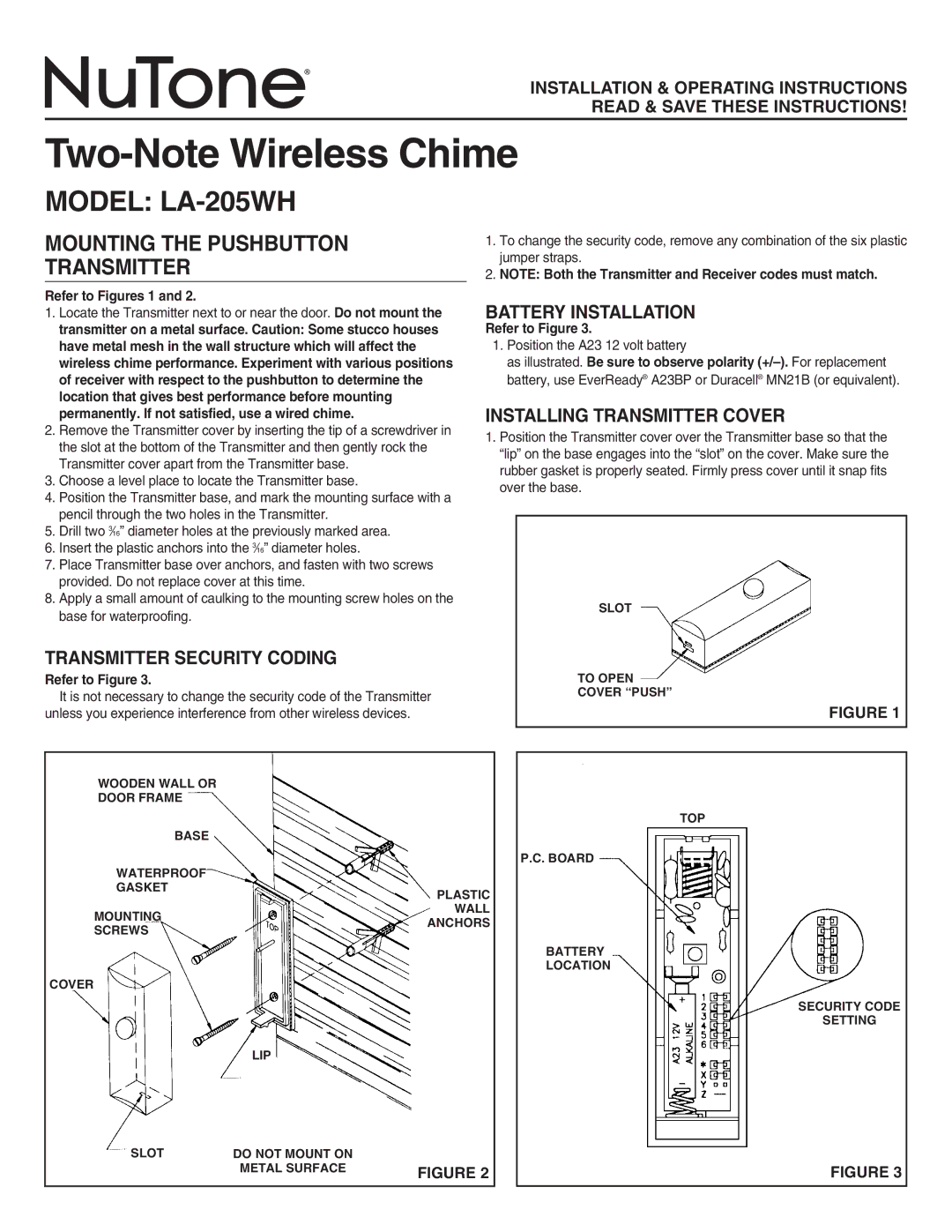
Refer to Figures 1 and 2.
1.To change the security code, remove any combination of the six plastic jumper straps.
2.NOTE: Both the Transmitter and Receiver codes must match.
1. | Locate the Transmitter next to or near the door. Do not mount the | BATTERY INSTALLATION | ||
| transmitter on a metal surface. Caution: Some stucco houses | Refer to Figure 3. | ||
| have metal mesh in the wall structure which will affect the | 1. Position the A23 12 volt battery | ||
| wireless chime performance. Experiment with various positions |
| as illustrated. Be sure to observe polarity | |
| of receiver with respect to the pushbutton to determine the |
| battery, use EverReady® A23BP or Duracell® MN21B (or equivalent). | |
| location that gives best performance before mounting | INSTALLING TRANSMITTER COVER | ||
| permanently. If not satisfied, use a wired chime. | |||
2. | Remove the Transmitter cover by inserting the tip of a screwdriver in | 1. Position the Transmitter cover over the Transmitter base so that the | ||
| the slot at the bottom of the Transmitter and then gently rock the | |||
|
| “lip” on the base engages into the “slot” on the cover. Make sure the | ||
| Transmitter cover apart from the Transmitter base. |
| ||
|
| rubber gasket is properly seated. Firmly press cover until it snap fits | ||
3. | Choose a level place to locate the Transmitter base. |
| ||
| over the base. | |||
4. | Position the Transmitter base, and mark the mounting surface with a |
| ||
|
|
| ||
| pencil through the two holes in the Transmitter. |
|
|
|
|
|
|
| |
5. | Drill two 3⁄16” diameter holes at the previously marked area. |
|
|
|
6. | Insert the plastic anchors into the 3⁄16” diameter holes. |
|
|
|
7. | Place Transmitter base over anchors, and fasten with two screws |
|
|
|
| provided. Do not replace cover at this time. |
|
|
|
8. | Apply a small amount of caulking to the mounting screw holes on the |
|
| SLOT |
| base for waterproofing. |
|
| |
|
|
|
| |
TRANSMITTER SECURITY CODING |
|
|
| |
Refer to Figure 3. |
|
| TO OPEN | |
| It is not necessary to change the security code of the Transmitter |
|
| COVER “PUSH” |
unless you experience interference from other wireless devices. |
|
| FIGURE 1 | |
|
|
|
|
|
|
|
|
|
|
| WOODEN WALL OR |
|
|
|
| DOOR FRAME |
|
|
|
|
|
|
| TOP |
| BASE |
|
|
|
P.C. BOARD
WATERPROOF
GASKET
PLASTIC
WALL
MOUNTINGANCHORS
SCREWS
BATTERY
LOCATION
COVER
SECURITY CODE
SETTING
LIP
SLOT | DO NOT MOUNT ON |
|
| METAL SURFACE | FIGURE 2 |
FIGURE 3