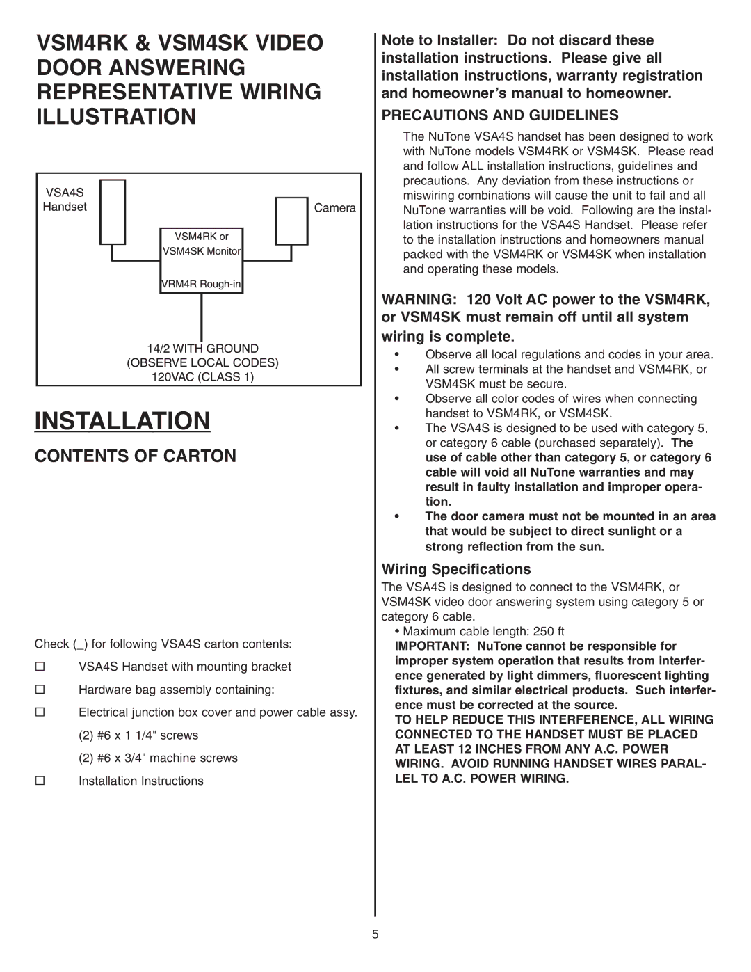
VSM4RK & VSM4SK VIDEO DOOR ANSWERING REPRESENTATIVE WIRING ILLUSTRATION
INSTALLATION
CONTENTS OF CARTON
Check (_) for following VSA4S carton contents:
♦VSA4S Handset with mounting bracket
♦Hardware bag assembly containing:
♦Electrical junction box cover and power cable assy.
(2) #6 x 1 1/4" screws
(2) #6 x 3/4" machine screws
♦Installation Instructions
Note to Installer: Do not discard these installation instructions. Please give all installation instructions, warranty registration and homeowner’s manual to homeowner.
PRECAUTIONS AND GUIDELINES
The NuTone VSA4S handset has been designed to work with NuTone models VSM4RK or VSM4SK. Please read and follow ALL installation instructions, guidelines and precautions. Any deviation from these instructions or miswiring combinations will cause the unit to fail and all NuTone warranties will be void. Following are the instal- lation instructions for the VSA4S Handset. Please refer to the installation instructions and homeowners manual packed with the VSM4RK or VSM4SK when installation and operating these models.
WARNING: 120 Volt AC power to the VSM4RK, or VSM4SK must remain off until all system wiring is complete.
•Observe all local regulations and codes in your area.
•All screw terminals at the handset and VSM4RK, or VSM4SK must be secure.
•Observe all color codes of wires when connecting handset to VSM4RK, or VSM4SK.
•The VSA4S is designed to be used with category 5, or category 6 cable (purchased separately). The use of cable other than category 5, or category 6 cable will void all NuTone warranties and may result in faulty installation and improper opera- tion.
•The door camera must not be mounted in an area that would be subject to direct sunlight or a strong reflection from the sun.
Wiring Specifications
The VSA4S is designed to connect to the VSM4RK, or VSM4SK video door answering system using category 5 or category 6 cable.
• Maximum cable length: 250 ft
IMPORTANT: NuTone cannot be responsible for improper system operation that results from interfer- ence generated by light dimmers, fluorescent lighting fixtures, and similar electrical products. Such interfer- ence must be corrected at the source.
TO HELP REDUCE THIS INTERFERENCE, ALL WIRING CONNECTED TO THE HANDSET MUST BE PLACED AT LEAST 12 INCHES FROM ANY A.C. POWER WIRING. AVOID RUNNING HANDSET WIRES PARAL- LEL TO A.C. POWER WIRING.
5