OPTICAL TERMINOLOGY
9. Aberrations
A difference between an ideal image and an actual image that passes through an optical system is called an “aberration.”
9.1 Requirements for Ideal Image Formation
The following three requirements must be satisfied to form an image with no aberration, or an ideal image.
(i)All the light rays coming from a single point and passing through an image formation optical system converge on a single point.
(ii)Image points, which correspond to object points on the same plane perpendicular to the optical axis, are present on the same plane.
(iii)The planar shape of an object and the planar shape of an image that are on the same plane perpendicular to the optical axis have a similarity relation.
Figure 9-1 Requirements for Ideal Image Formation
(i) | (ii) | (iii) |
Object Image plane |
|
|
In an actual optical system, however, it is very difficult to strictly meet the requirements for ideal image formation and this causes “aberrations” that interfere with image forming performance.
9.2 Classification of Aberrations
Aberrations that interfere with image forming performance are classified as shown below in Figure
Seidel’s aberration = “Expansion of a point image” + “Curvature of image plane” + “Deformation”
Figure 9-2 Classification of Aberrations
characteristics of glass materials used for the optical system. “Expansion of a point image” can also be expressed by “wavefront aberration” that regards the light as “waves” and takes account of the phase to include the influence of diffraction.
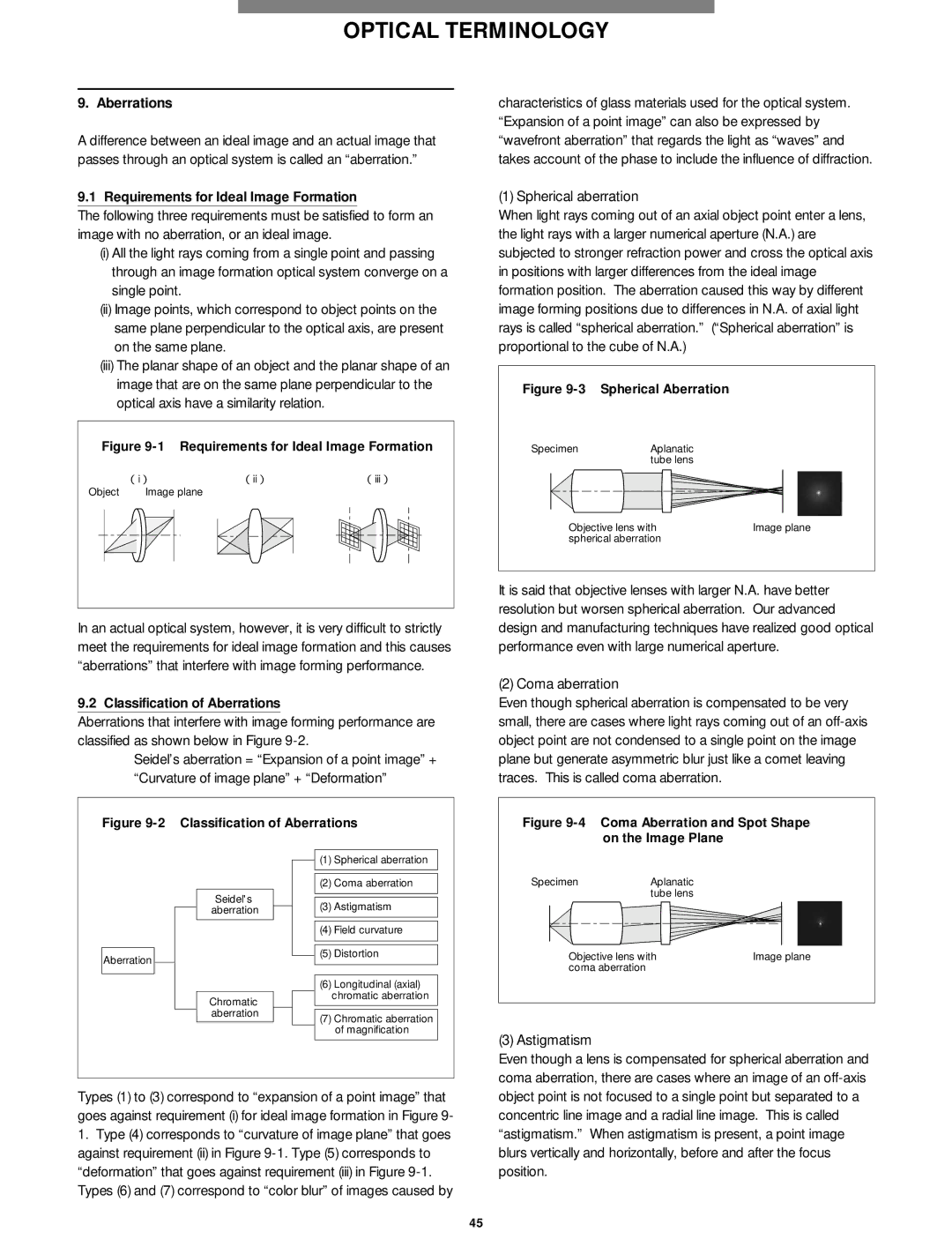
(1) Spherical aberration
When light rays coming out of an axial object point enter a lens, the light rays with a larger numerical aperture (N.A.) are subjected to stronger refraction power and cross the optical axis in positions with larger differences from the ideal image formation position. The aberration caused this way by different image forming positions due to differences in N.A. of axial light rays is called “spherical aberration.” (“Spherical aberration” is proportional to the cube of N.A.)
Figure |
| |
Specimen | Aplanatic |
|
| tube lens |
|
Objective lens with | Image plane | |
spherical aberration |
| |
It is said that objective lenses with larger N.A. have better resolution but worsen spherical aberration. Our advanced design and manufacturing techniques have realized good optical performance even with large numerical aperture.
(2) Coma aberration
Even though spherical aberration is compensated to be very small, there are cases where light rays coming out of an
Figure 9-4 Coma Aberration and Spot Shape on the Image Plane
Aberration
Seidel's aberration
Chromatic aberration
![]()
![]() (1) Spherical aberration
(1) Spherical aberration
(2) Coma aberration
(3) Astigmatism
(4)Field curvature
![]()
![]() (5) Distortion
(5) Distortion
(6)Longitudinal (axial) chromatic aberration
(7)Chromatic aberration of magnification
Specimen | Aplanatic |
|
| tube lens |
|
Objective lens with | Image plane | |
coma aberration |
|
|
(3) Astigmatism
Types (1) to (3) correspond to “expansion of a point image” that goes against requirement (i) for ideal image formation in Figure 9-
1.Type (4) corresponds to “curvature of image plane” that goes against requirement (ii) in Figure
Even though a lens is compensated for spherical aberration and coma aberration, there are cases where an image of an
45