1-11

V and I output

1-12

1-13

1-14

No communi- cation

1-15

1-16

1-17

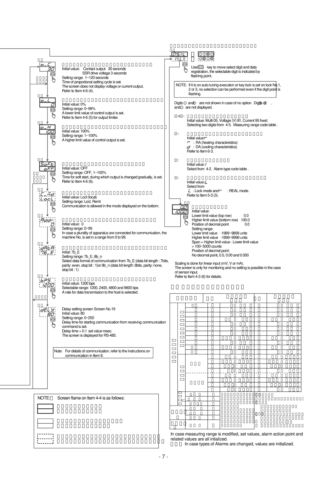
Proportional cycle setting screen (screen No.11) Initial value: Contact output 30 seconds

SSR drive voltage 3 seconds

Setting range: 1~120 seconds

Time of proportional setting cycle is set.

The screen does not display voltage or current output. Refer to Item 4-6 (4).

Lower limit output limiter setting screen (screen No.12) Initial value: 0%

Setting range: 0~99%

A lower limit value of control output is set.

Refer to Item 4-6 (5) for output limiter.

Higher limit output limiter setting screen (screen No.13) Initial value: 100%

Setting range: 1~100%

A higher limit value of control output is set.

Soft start time setting screen (screen No.14)

Initial value: OFF

Setting range: OFF, 1~100%

Time for soft start, during which output is changed gradually, is set. Refer to Item 4-6 (6).

Communication mode selecting screen (screen No.15) Initial value: Locl (local)

Setting range: Locl, Remt

Communication is allowed in the mode displayed on the bottom.

Communication address setting screen (screen No.16) Initial value: 0

Setting range: 0~99

In case a plurality of apparatus are connected for communication, the machine No. is set in a range from 0 to 99.

Mode 2 Screen Group (Function selecting screen)

2-0

=

1

2

3

4

=

5

6

7

8


Use ENT key to move select digit and data registration, the selectable digit is indicated by flashing point.

NOTE: If it is on auto tuning execution or key lock is set on lock No.1, 2 or 3, no selection can be performed even if the digit point is flashing.

Digits 5 and 7 are not shown in case of no option. Digits of 3 , 6 and 8 are not displayed.

12 : Measuring range code select digit

Initial value: Multi 05, Voltage (V) 81, Current 95 fixed. Selecting two digits from “4-5. Measuring range code table”.

4: Control output characteristic select digit

Initial value:

:RA (heating characteristics)

:DA (cooling characteristics)

Refer to Item 6-3.

5 : Alarm type select digit

Initial value:

Select from “4-2. Alarm type code table”.

7: Heater break alarm action mode select digit

Initial value: Select from


: Lock mode and

: REAL mode.

Refer to Item 5-3 (3).


2-1


Input scaling screen


Initial value:


Lower limit value (top row)

0.0


Higher limit value (bottom row)

100.0


Position of decimal point

0.0


Setting range:


Lower limit value

-1999~9899 units


Higher limit value

-1899~9999 units

Span = Higher limit value - Lower limit value

Communication data format selection screen (screen No.17)

Initial: 7b_E

Setting range: 7b_E, 8b_n

Select data format of communication from 7b_E (data bit length : 7bits,

parity: even, stop bit : 1)or 8b_n (data bit length: 8bits, parity: none,

stop bit : 1)

1-18

Communication rate selecting screen (screen No.18)

Initial value: 1200 bps

Selectable range: 1200, 2400, 4800 and 9600 bps

A rate for data transmission to the host is selected.

RS-422A

1-19

Delay setting screen Screen No.19 Initial value: 80

Setting range: 0~255

Delay time for starting communication from receiving communication command is set.

Delay time = 0.1 set value msec. The screen is displayed for RS-485.

Note: For details of communication, refer to the instructions on communication in Item 8.

NOTE: Screen flame on Item 4-4 is as follows:

Screens always shown during key operation.

Screens shown during case with option or selected option.

Screens shown or skipped depending on the type of output or the setting status of control action mode.

=100~5000 counts Position of decimal point:

No decimal point, 0.0, 0.00 and 0.000

Scaling is done for linear input (mV, V or mA).

The screen is only for monitoring and no setting is possible in the case of sensor input.

Refer to Item 4-3 (6) for details.

4-5. Measuring range code table


Input type


Code

Measuring


Code

Measuring


Range


Range


*1B

01

0

~

1800°C

12

0

~

3300°F


input


R

02

0

~

1700°C

13

0

~

3100°F


K

04

-100

~

400°C

15

-150

~

750°F


S

03

0

~

1700°C

14

0

~

3100°F

input


Thermocouple


*2 L

11

0

~

600°C

22

0

~

1100°F


K

05

0

~

1200°C

16

0

~

2200°F


E

06

0

~

700°C

17

0

~

1300°F


J


07

0

~

600°C

18

0

~

1100°F


T

08

-199.9 ~

200.0°C

19

-300 ~

400°F


N

09

0

~

1300°C

20

0

~

2300°F


*2 U

10

-199.9 ~

200.0°C

21

-300 ~

400°F

Multi


32

-100.0

~

100.0°C

40

-150.0

~

200.0°F


31

-200

~

600°C

39

-300

~

-1100°F


Pt 100


D.


33

-50.0 ~

50.0°C

41

-50.0 ~

120.0°F


34

0.0

~

200.0°C

42

0

~

400°F


T.


35

-200 ~

600°C

43

-300 ~

-1100°F


R.


JPt 100

36

-100.0 ~

100.0°C

44

-150.0 ~

200.0°F


37

-50.0 ~

50.0°C

45

-50.0 ~

120.0°F


38

0.0

~

200.0

°

C

46

0

~

400 F


Voltage mV

0

~

100

73


R. T. D.


°


Scaling setting range:


0

~

10

71

Initial value: 0.0~100.0

Thermocouple


10

~

50

72

Conditions of scaling


B, R, S, K, E, J, T, N: JIS/ANSI/IEC


0

~

1

81

-1999~9999,


Pt100 : Present JIS/IEC

Voltage

Span: 100~5000 counts

JPt100 : Former JIS

0

~

5

82


V

Position of decimal point:

*1 Thermocouple B: Accuracy not


0

~

10

83

No decimal point, the


guaranteed for temperatures

Current

4

~

20

95

first, second and third


below 400 °C (750 °F).

decimal places


*2 Thermocouple U, L: DIN43710

mA


In case measuring range is modified, set values, alarm action point and other related values are all intialized.

NOTE: In case types of Alarms are changed, values are initialized.

- 7 -

Page 9
Image 9
Omega CN155, CN154, CN158, CN159 manual Measuring range code table, Soft start time setting screen screen No.14

CN159, CN155, CN158, CN154 specifications

Omega watches have long been celebrated for their precision, durability, and innovative features, and models such as the CN154, CN158, CN155, and CN159 exemplify these qualities. Each of these timepieces showcases Omega's commitment to craftsmanship and cutting-edge technology.

The Omega CN154 model is notable for its sleek design, combining elegance with robust functionality. Its stainless-steel case ensures durability while maintaining a lightweight feel. The watch features a mesmerizing sapphire crystal that provides scratch resistance and enhances visibility, allowing wearers to appreciate the intricate dial details. Equipped with Omega's Co-Axial escapement technology, the CN154 offers exceptional accuracy and reduced friction, resulting in a longer service life.

Similarly, the Omega CN158 stands out with its distinctive aesthetic and advanced technical features. This model incorporates the brand's renowned chronometer certification, guaranteeing its precision. The CN158 utilizes a helium escape valve, an essential feature for professional divers, enabling it to withstand high pressures during underwater activities. The luminous hands and markers ensure visibility in low-light environments, making it ideal for both diving adventures and everyday wear.

The CN155 model focuses on functionality without compromising style. Its tachymetric scale on the bezel allows for precise speed calculations, catering to motorsport enthusiasts. The chronograph feature provides accurate timing capabilities, while the stainless-steel bracelet offers comfort and security. The watch's water resistance up to 300 meters enhances its versatility, making it a reliable companion for any occasion, be it a business meeting or an ocean dive.

Lastly, the Omega CN159 encapsulates luxury and performance. With a striking ceramic bezel and an intricately designed dial, this timepiece makes a bold statement. The CN159 is equipped with Omega's Master Chronometer technology, which ensures precision while also being resistant to magnetic interference. This allows it to maintain accuracy even in environments with strong magnetic fields. The watch also features a transparent case back, showcasing the exquisite craftsmanship of the automatic movement within.

In summary, the Omega CN154, CN158, CN155, and CN159 models represent the pinnacle of watchmaking innovation. They combine style, precision, and advanced technologies, making them excellent choices for discerning watch enthusiasts. Whether for professional use or personal style, these timepieces offer something for everyone, ensuring Omega remains a leader in the luxury watch industry.