P R E - I N S TA L L AT I O N C O N S I D E R AT I O N S
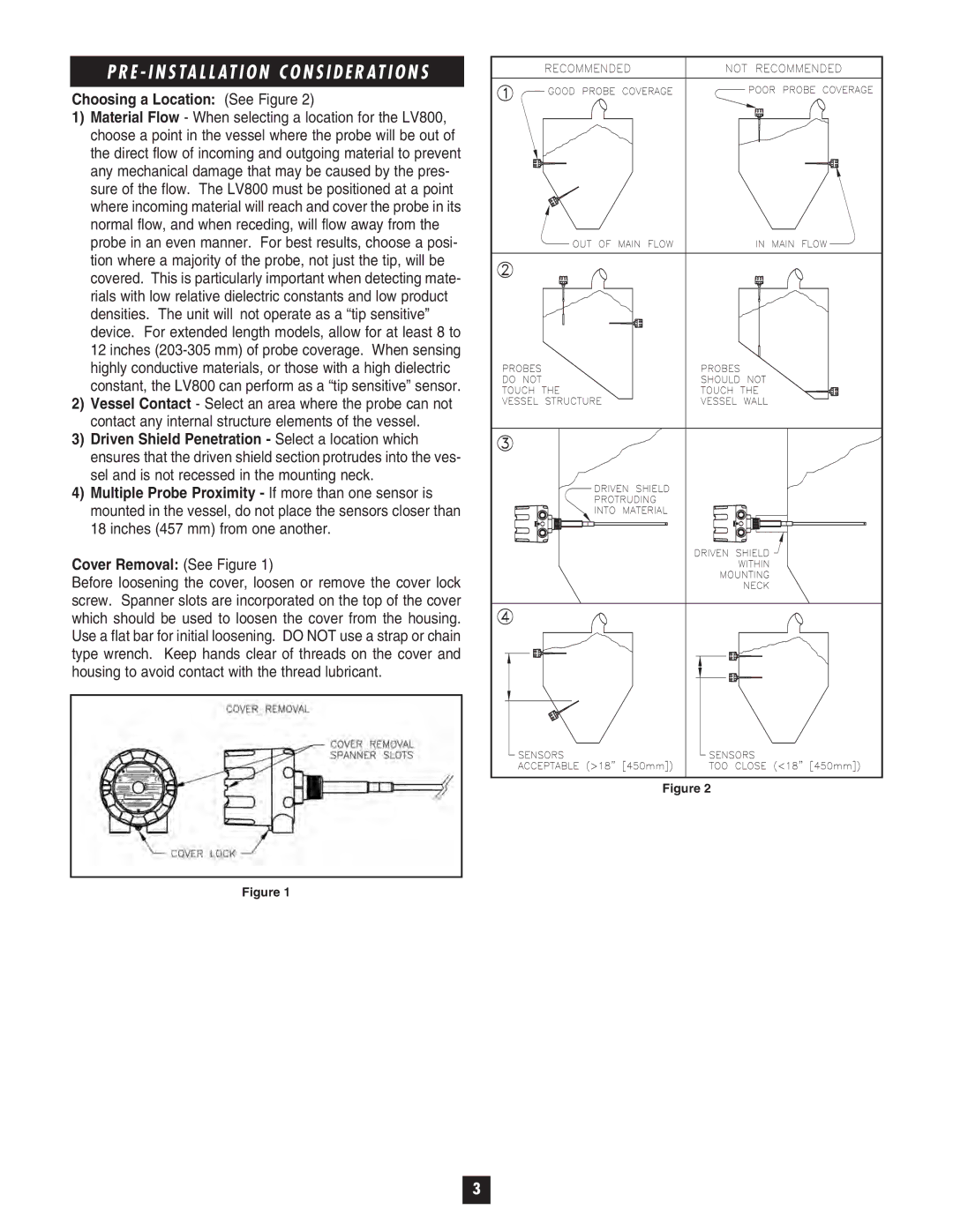
Choosing a Location: (See Figure 2)
1)Material Flow - When selecting a location for the LV800, choose a point in the vessel where the probe will be out of
the direct flow of incoming and outgoing material to prevent any mechanical damage that may be caused by the pres- sure of the flow. The LV800 must be positioned at a point where incoming material will reach and cover the probe in its normal flow, and when receding, will flow away from the probe in an even manner. For best results, choose a posi- tion where a majority of the probe, not just the tip, will be covered. This is particularly important when detecting mate- rials with low relative dielectric constants and low product densities. The unit will not operate as a “tip sensitive” device. For extended length models, allow for at least 8 to 12 inches
2)Vessel Contact - Select an area where the probe can not contact any internal structure elements of the vessel.
3)Driven Shield Penetration - Select a location which ensures that the driven shield section protrudes into the ves- sel and is not recessed in the mounting neck.
4)Multiple Probe Proximity - If more than one sensor is
mounted in the vessel, do not place the sensors closer than 18 inches (457 mm) from one another.
Cover Removal: (See Figure 1)
Before loosening the cover, loosen or remove the cover lock screw. Spanner slots are incorporated on the top of the cover which should be used to loosen the cover from the housing. Use a flat bar for initial loosening. DO NOT use a strap or chain type wrench. Keep hands clear of threads on the cover and housing to avoid contact with the thread lubricant.
Figure 2
Figure 1
3
