LV800
Figure 7
Delay:
A potentiometer is provided for setting the time delay between the time material is "sensed" (Yellow LED on) and the time the relay contact output changes (Red LED on). Units have a 1- turn potentiometer. A clockwise rotation will increase the delay from .25 to 15 seconds. This adjustment minimizes false sig- nals associated with temporary material shifts. The delay between the time material is "not sensed" (Yellows LED off) and the time the relay contact output changes (Red LED off) is fixed at .25 seconds.
The term
High
Low
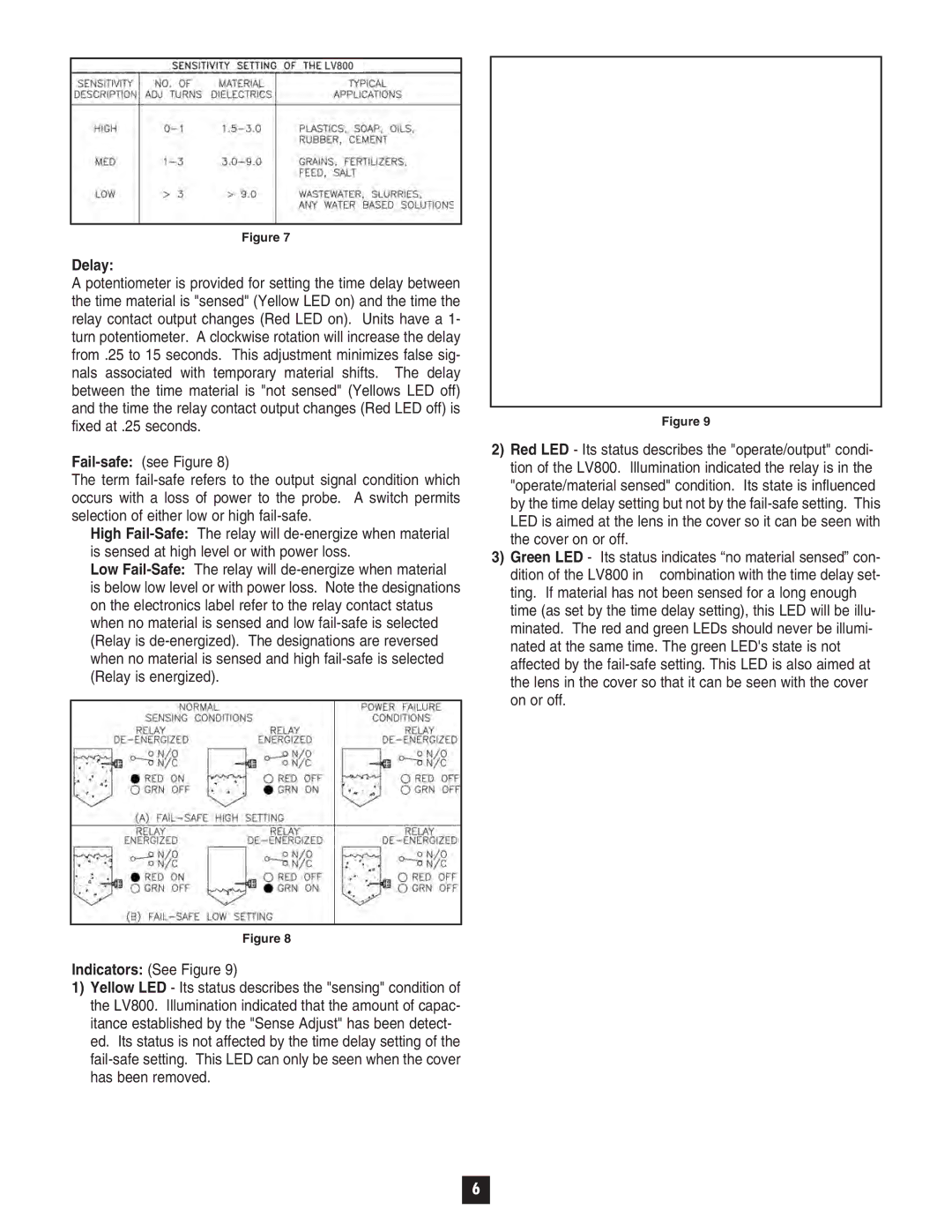
Figure 9
2)Red LED - Its status describes the "operate/output" condi- tion of the LV800. Illumination indicated the relay is in the "operate/material sensed" condition. Its state is influenced by the time delay setting but not by the
3)Green LED - Its status indicates “no material sensed” con-
dition of the LV800 in combination with the time delay set- ting. If material has not been sensed for a long enough time (as set by the time delay setting), this LED will be illu- minated. The red and green LEDs should never be illumi- nated at the same time. The green LED's state is not affected by the
Figure 8
Indicators: (See Figure 9)
1)Yellow LED - Its status describes the "sensing" condition of the LV800. Illumination indicated that the amount of capac- itance established by the "Sense Adjust" has been detect- ed. Its status is not affected by the time delay setting of the
6