Power Input: (See Figure5)
The LV800 is designed to accept either 115VAC or 230VAC (factory set). Verify the intended voltage supply is compatible with the voltage configuration indicated on the electronics and the external nameplate. Connect power as shown in Figure 5. Select wire size that can deliver suitable voltage and current for the application.
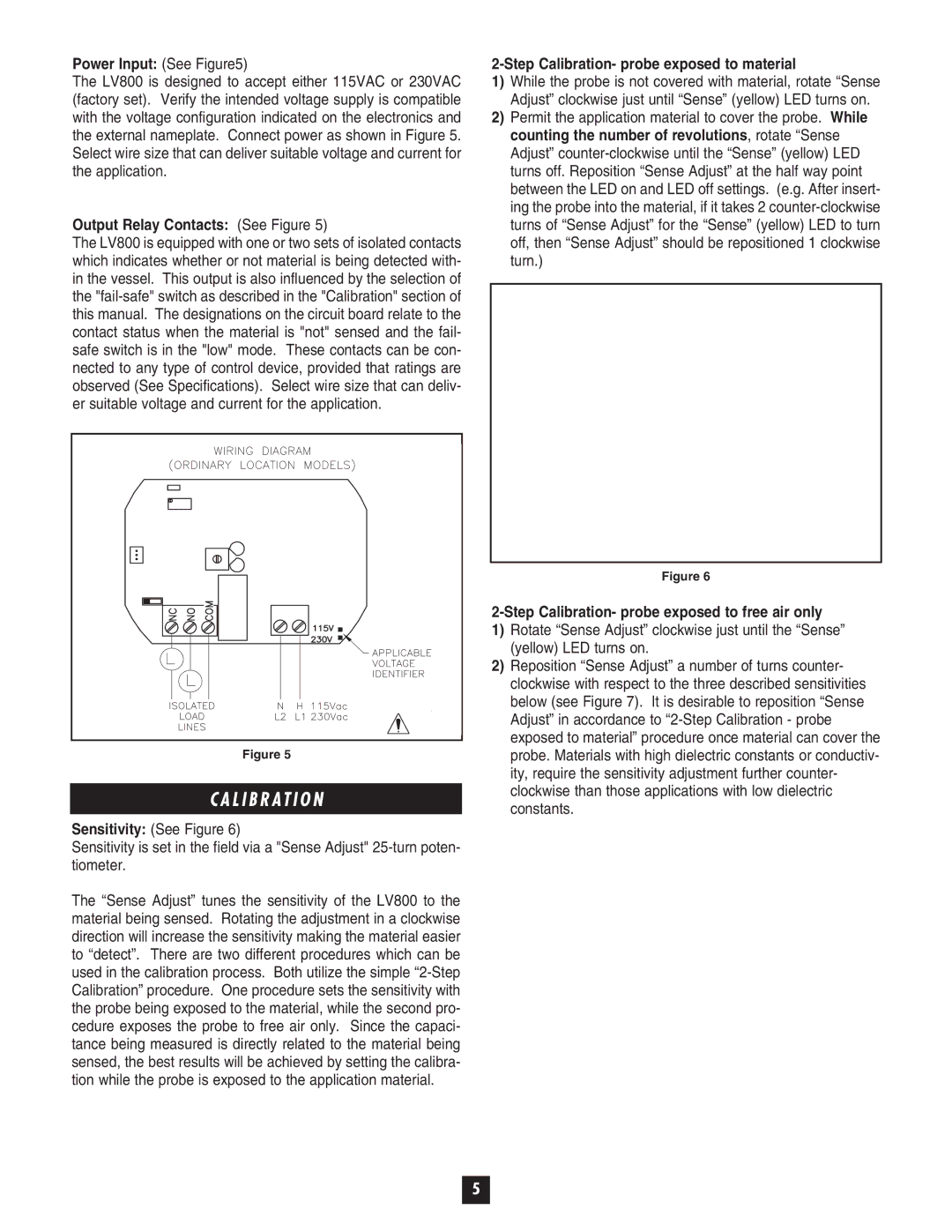
Output Relay Contacts: (See Figure 5)
The LV800 is equipped with one or two sets of isolated contacts which indicates whether or not material is being detected with- in the vessel. This output is also influenced by the selection of the
2-Step Calibration- probe exposed to material
1)While the probe is not covered with material, rotate “Sense Adjust” clockwise just until “Sense” (yellow) LED turns on.
2)Permit the application material to cover the probe. While counting the number of revolutions, rotate “Sense Adjust”
Figure 5
C A L I B R AT I O N
Sensitivity: (See Figure 6)
Sensitivity is set in the field via a "Sense Adjust"
The “Sense Adjust” tunes the sensitivity of the LV800 to the material being sensed. Rotating the adjustment in a clockwise direction will increase the sensitivity making the material easier to “detect”. There are two different procedures which can be used in the calibration process. Both utilize the simple
Figure 6
2-Step Calibration- probe exposed to free air only
1)Rotate “Sense Adjust” clockwise just until the “Sense” (yellow) LED turns on.
2)Reposition “Sense Adjust” a number of turns counter- clockwise with respect to the three described sensitivities below (see Figure 7). It is desirable to reposition “Sense Adjust” in accordance to
5