Installation 2
- ** means:
The following table lists the optional accessories:
| Accessories |
Model No. | Description |
Mounting Bracket | |
Water/Air Cooling Jacket with | |
Air Purge Collar | |
Laser Sighting | |
Regulated 24 VDC (400 mA) Power Supply | |
NIST Traceable Calibration |
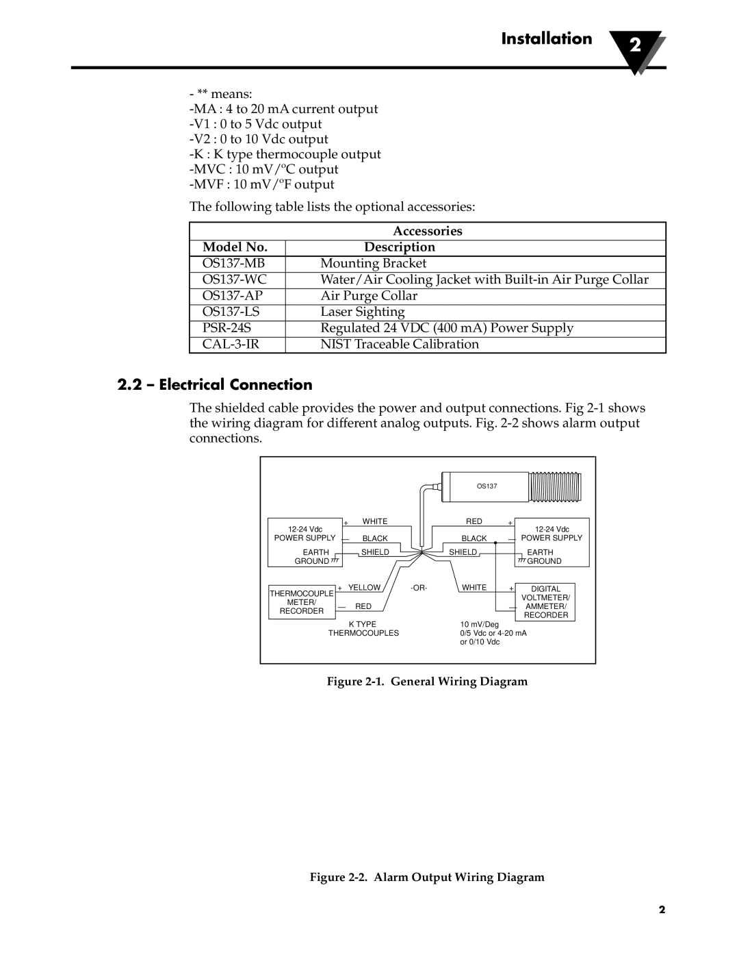
2.2 – Electrical Connection
The shielded cable provides the power and output connections. Fig
|
|
|
|
| OS137 |
|
|
| + | WHITE |
| RED | + | ||
|
|
|
|
|
| ||
POWER SUPPLY |
| – | BLACK |
| BLACK | – | POWER SUPPLY |
EARTH |
|
| SHIELD |
| SHIELD |
| EARTH |
GROUND |
|
|
|
|
|
| GROUND |
THERMOCOUPLE | + | YELLOW | WHITE | + | DIGITAL | ||
|
|
|
|
|
| VOLTMETER/ | |
METER/ |
|
|
|
|
|
| |
– |
| RED |
|
| – | AMMETER/ | |
RECORDER |
|
|
| ||||
|
|
|
|
|
| RECORDER | |
|
|
|
|
|
|
| |
|
|
| K TYPE |
| 10 mV/Deg |
|
|
THERMOCOUPLES |
| 0/5 Vdc or | |||||
|
|
|
|
| or 0/10 Vdc |
|
|
Figure 2-1. General Wiring Diagram
OS137 |
GREEN + |
MECHANICAL |
RELAY |
BLACK – |
Figure 2-2. Alarm Output Wiring Diagram
2