7.0 WIRING DIAGRAM
HAZARDOUS AREA |
|
| SAFE AREA | |
MODEL | 3 | 4 | SHUNT ZENER |
|
+ |
| SAFE AREA | ||
TX82B |
|
| DIODE | |
|
| APPARATUS | ||
INDICATOR | - |
| SAFETY | |
|
| |||
| INTER- |
| BARRIER |
|
|
|
|
| |
2 | CONNECTING |
| 1 | |
CABLES |
|
|
| |
|
|
|
| |
EARTHED BUS BAR
NOTES:
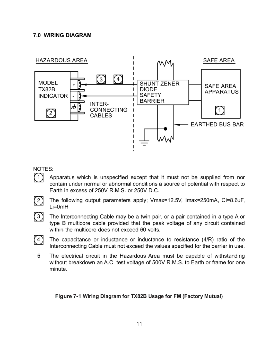
1Apparatus which is unspecified except that it must not be supplied from nor contain under normal or abnormal conditions a source of potential with respect to Earth in excess of 250V R.M.S. or 250V D.C.
2The following output parameters apply; Vmax=12.5V, Imax=250mA, Ci=8.6uF, Li=0mH
3The Interconnecting Cable may be a twin pair, or a pair contained in a type A or type B multicore cable provided that the peak voltage of any circuit contained within the multicore does not exceed 60 volts.
4The capacitance or inductance or inductance to resistance (4/R) ratio of the Interconnecting Cable must not exceed the values specified for the barrier in use.
5The electrical circuit in the Hazardous Area must be capable of withstanding without breakdown an A.C. test voltage of 500V R.M.S. to Earth or frame for one minute.
Figure 7-1 Wiring Diagram for TX82B Usage for FM (Factory Mutual)
11