DIN-191 & DIN-192 USERS MANUAL 6
isolated RS-485 input data lines will be re-amplified and retransmitted on the RS-485 OUT data lines.
.
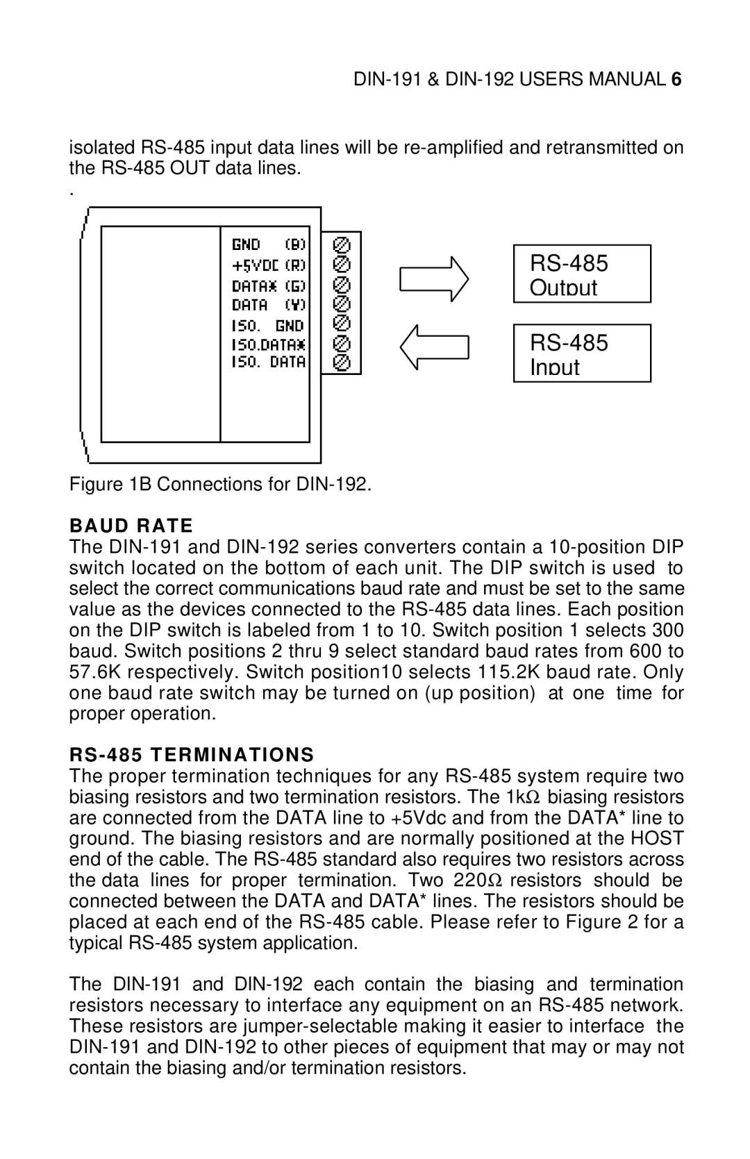
RS-485
Output
RS-485
Input
Figure 1B Connections for DIN-192.
BAUD RATE
The DIN-191 and DIN-192 series converters contain a 10-position DIP switch located on the bottom of each unit. The DIP switch is used to select the correct communications baud rate and must be set to the same value as the devices connected to the RS-485 data lines. Each position on the DIP switch is labeled from 1 to 10. Switch position 1 selects 300 baud. Switch positions 2 thru 9 select standard baud rates from 600 to 57.6K respectively. Switch position10 selects 115.2K baud rate. Only one baud rate switch may be turned on (up position) at one time for proper operation.
RS - 485 TERMINATIONS
The proper termination techniques for any RS-485 system require two biasing resistors and two termination resistors. The 1kΩ biasing resistors are connected from the DATA line to +5Vdc and from the DATA* line to ground. The biasing resistors and are normally positioned at the HOST end of the cable. The RS-485 standard also requires two resistors across the data lines for proper termination. Two 220Ω resistors should be connected between the DATA and DATA* lines. The resistors should be placed at each end of the RS-485 cable. Please refer to Figure 2 for a typical RS-485 system application.
The DIN-191 and DIN-192 each contain the biasing and termination resistors necessary to interface any equipment on an RS-485 network. These resistors are jumper-selectable making it easier to interface the DIN-191 and DIN-192 to other pieces of equipment that may or may not contain the biasing and/or termination resistors.