DIN-191 & DIN-192 USERS MANUAL 8
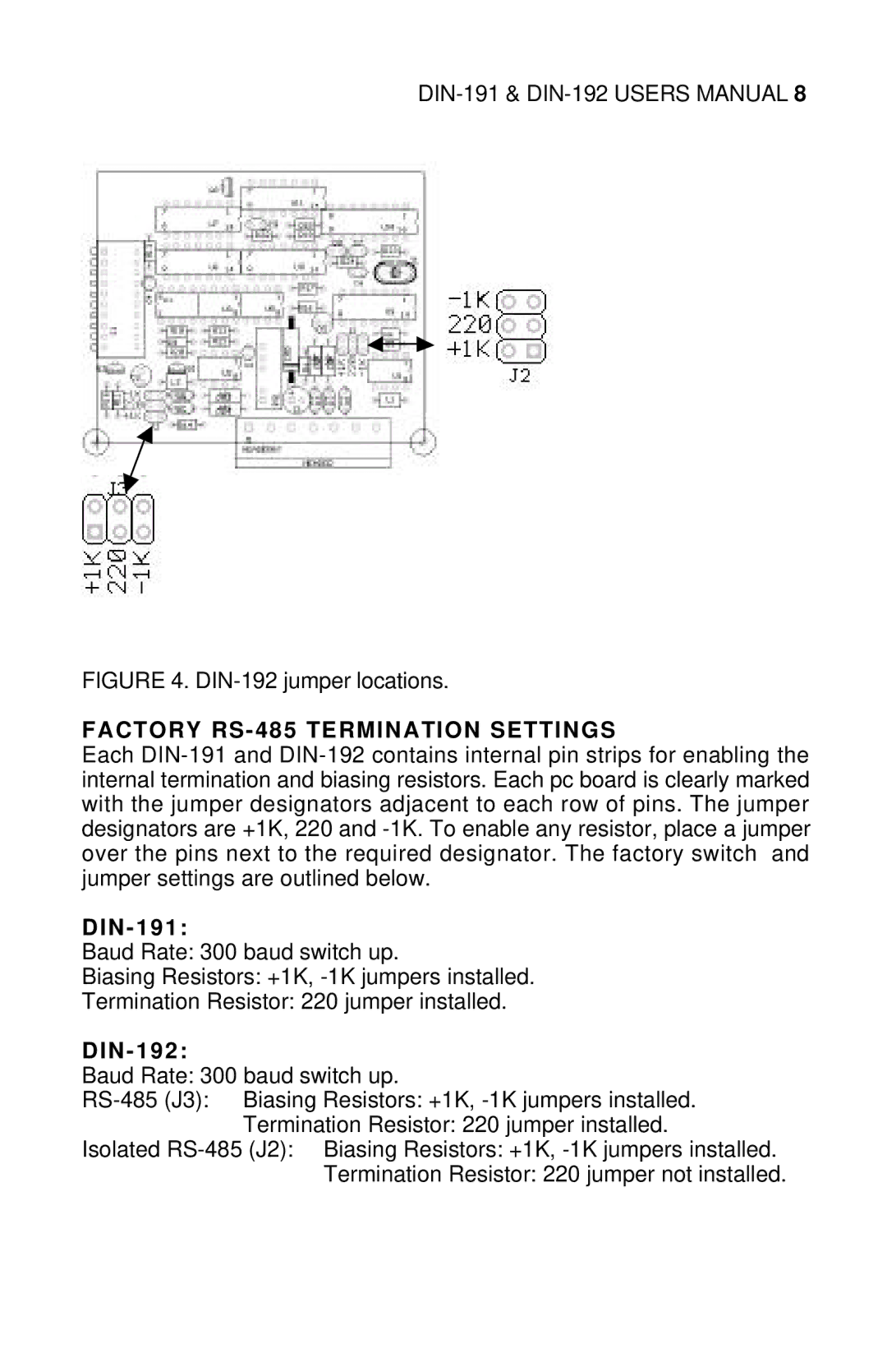
FIGURE 4. DIN-192 jumper locations.
FACTORY RS-485 TERMINATION SETTINGS
Each DIN-191 and DIN-192 contains internal pin strips for enabling the internal termination and biasing resistors. Each pc board is clearly marked with the jumper designators adjacent to each row of pins. The jumper designators are +1K, 220 and -1K. To enable any resistor, place a jumper over the pins next to the required designator. The factory switch and jumper settings are outlined below.
DIN - 191:
Baud Rate: 300 baud switch up.
Biasing Resistors: +1K, -1K jumpers installed.
Termination Resistor: 220 jumper installed.
DIN - 192:
Baud Rate: 300 baud switch up.
RS-485 (J3): Biasing Resistors: +1K, -1K jumpers installed. Termination Resistor: 220 jumper installed.
Isolated RS-485 (J2): Biasing Resistors: +1K, -1K jumpers installed. Termination Resistor: 220 jumper not installed.