ASSEMBLY WARNING
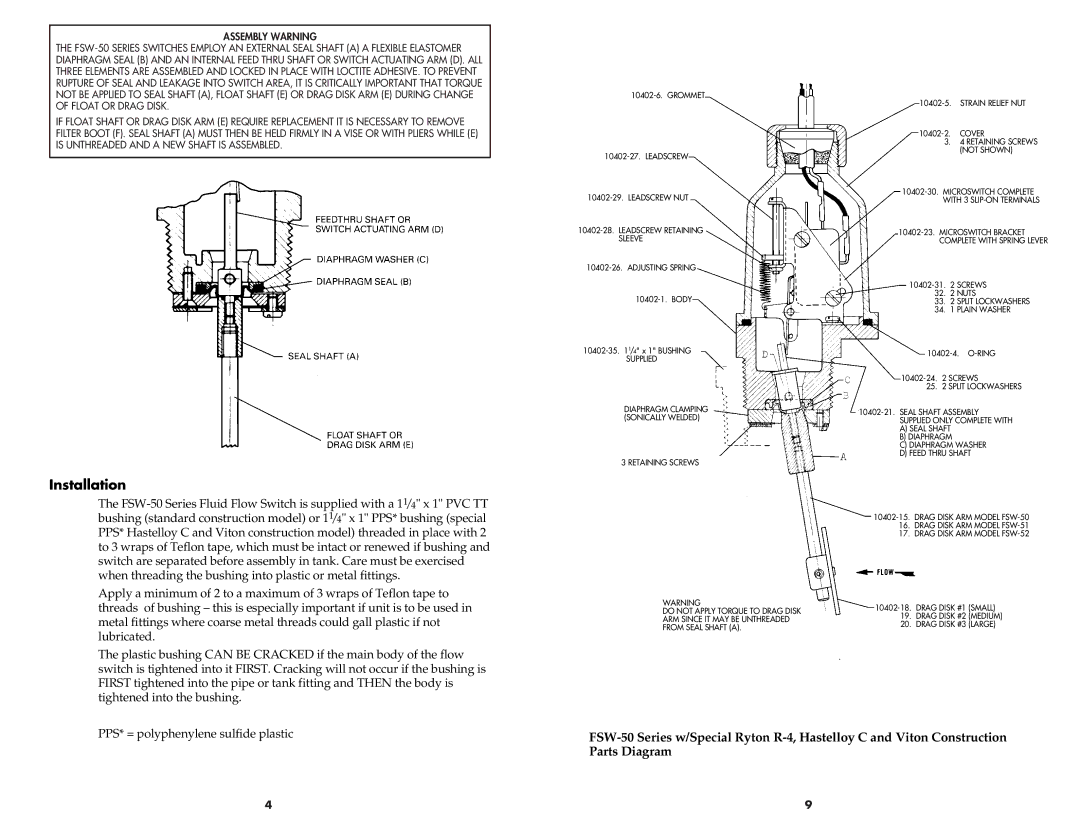
THE FSW-50 SERIES SWITCHES EMPLOY AN EXTERNAL SEAL SHAFT (A) A FLEXIBLE ELASTOMER DIAPHRAGM SEAL (B) AND AN INTERNAL FEED THRU SHAFT OR SWITCH ACTUATING ARM (D). ALL THREE ELEMENTS ARE ASSEMBLED AND LOCKED IN PLACE WITH LOCTITE ADHESIVE. TO PREVENT RUPTURE OF SEAL AND LEAKAGE INTO SWITCH AREA, IT IS CRITICALLY IMPORTANT THAT TORQUE NOT BE APPLIED TO SEAL SHAFT (A), FLOAT SHAFT (E) OR DRAG DISK ARM (E) DURING CHANGE OF FLOAT OR DRAG DISK.
IF FLOAT SHAFT OR DRAG DISK ARM (E) REQUIRE REPLACEMENT IT IS NECESSARY TO REMOVE FILTER BOOT (F). SEAL SHAFT (A) MUST THEN BE HELD FIRMLY IN A VISE OR WITH PLIERS WHILE (E) IS UNTHREADED AND A NEW SHAFT IS ASSEMBLED.
Installation
The FSW-50 Series Fluid Flow Switch is supplied with a 11/4" x 1" PVC TT bushing (standard construction model) or 11/4" x 1" PPS* bushing (special PPS* Hastelloy C and Viton construction model) threaded in place with 2 to 3 wraps of Teflon tape, which must be intact or renewed if bushing and switch are separated before assembly in tank. Care must be exercised when threading the bushing into plastic or metal fittings.
Apply a minimum of 2 to a maximum of 3 wraps of Teflon tape to threads of bushing – this is especially important if unit is to be used in metal fittings where coarse metal threads could gall plastic if not lubricated.
The plastic bushing CAN BE CRACKED if the main body of the flow switch is tightened into it FIRST. Cracking will not occur if the bushing is FIRST tightened into the pipe or tank fitting and THEN the body is tightened into the bushing.
10402-6. GROMMET
10402-27. LEADSCREW
10402-29. LEADSCREW NUT
10402-28. LEADSCREW RETAINING SLEEVE
10402-26. ADJUSTING SPRING
10402-1. BODY
10402-35. 11/4" x 1" BUSHING SUPPLIED
DIAPHRAGM CLAMPING (SONICALLY WELDED)
3 RETAINING SCREWS
WARNING
DO NOT APPLY TORQUE TO DRAG DISK
ARM SINCE IT MAY BE UNTHREADED
FROM SEAL SHAFT (A).
10402-5. STRAIN RELIEF NUT
10402-2. COVER
3.4 RETAINING SCREWS (NOT SHOWN)
10402-30. MICROSWITCH COMPLETE WITH 3 SLIP-ON TERMINALS
10402-23. MICROSWITCH BRACKET COMPLETE WITH SPRING LEVER
10402-31. 2 SCREWS
32.2 NUTS
33.2 SPLIT LOCKWASHERS
34.1 PLAIN WASHER
10402-4. O-RING
10402-24. 2 SCREWS
25. 2 SPLIT LOCKWASHERS
10402-21. SEAL SHAFT ASSEMBLY SUPPLIED ONLY COMPLETE WITH
A)SEAL SHAFT
B)DIAPHRAGM
C)DIAPHRAGM WASHER
D)FEED THRU SHAFT
10402-15. DRAG DISK ARM MODEL FSW-50
16.DRAG DISK ARM MODEL FSW-51
17.DRAG DISK ARM MODEL FSW-52
10402-18. DRAG DISK #1 (SMALL)
19.DRAG DISK #2 (MEDIUM)
20.DRAG DISK #3 (LARGE)