3 RETAINING SCREWS
FLEXIBLE DRAG STRIP ASSEMBLY
IS AVAILABLE TO REPLACE DRAG
DISK AND DRAG DISK ARM. NO
FILTER BOOT IS USED.
38. CLAMP WASHER
39. DAMPENER WASHER
40. SCREW x 3/8" LONG
41. 2 PLAIN WASHERS
42. SPLIT LOCK WASHER
10398-5. STRAIN RELIEF NUT
10398-2. COVER
3.4 RETAINING SCREWS (NOT SHOWN)
33.2 NUTS
34.2 SPLIT LOCKWASHERS
35.1 PLAIN WASHER
26. 2 SPLIT LOCKWASHERS
A)SEAL SHAFT
B)DIAPHRAGM
C)DIAPHRAGM WASHER
D)FEED THRU SHAFT
17.DRAG DISK ARM MODEL
18.DRAG DISK ARM MODEL
20.DRAG DISK #2 (MEDIUM)
21.DRAG DISK #3 (LARGE)
WARNING
DO NOT APPLY TORQUE TO DRAG DISK
ARM SINCE IT MAY BE UNTHREADED
FROM SEAL SHAFT (A).
Thus: 1. Teflon tape thread and tighten the plastic bushing into the pipe or tank fitting.
2.Teflon tape thread and tighten the switch into the PLASTIC bushing by applying a wrench to the hexagon section. Repeat steps 1 and 2 until the ARROW on the body points in the DIRECTION OF FLOW and threads are leak tight.
NOTE
Plumber’s tools such as pipe wrenches are not recommended. If possible, use a ‘Rigid’ type wrench where the smooth jaws closely fit the hexagon section.
Electrical Wiring
1.Remove gland nut, grommet and switch cover.
2.Strip outer jacket of electrical cord back approximately 11/4 inches. Strip insulation from individual conductors back approximately
1/4 inch.
3.Slip on terminals are supplied with each switch. Remove from switch terminals and crimp on or solder to electrical leads.
4.Feed electrical cable through gland nut, grommet and switch cover as shown.
5.Apply slip on terminals to appropriate contacts of microswitch.
6.Slide the cover down the cable and fasten to the body of the switch with 4 screws provided.
7.Slide the grommet down the cable until the outer jacket is level with the small end of the grommet.
8.Push the grommet into the tapered end of the cover. Hold the cable jacket to prevent rotation and thread the gland nut firmly on to the cover.
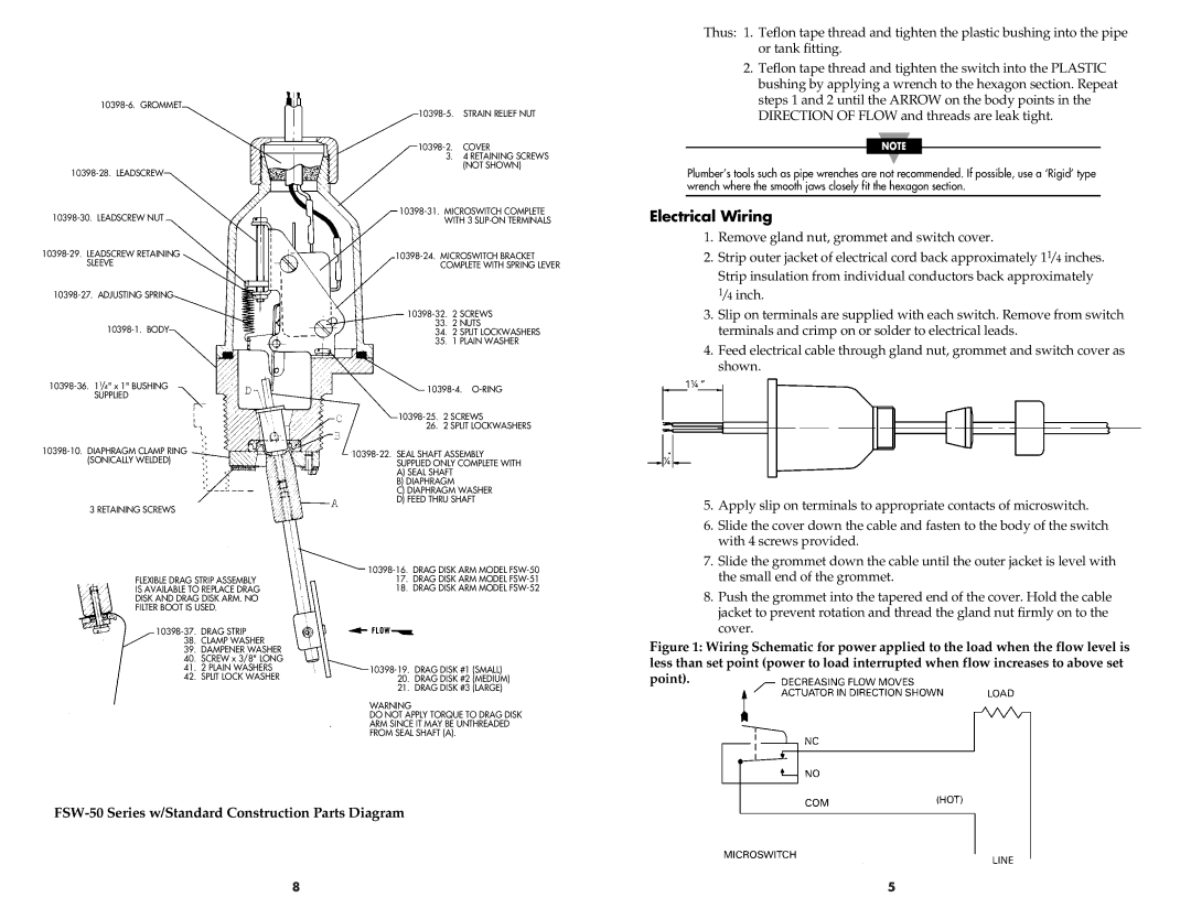
Figure 1: Wiring Schematic for power applied to the load when the flow level is less than set point (power to load interrupted when flow increases to above set point).
8 | 5 |