START HERE
Using this Quick Start Manual
Use this Quick Start Manual with your OS530E/ OS520E series Handheld Infrared Thermometer to set up and perform basic operations. These tasks are:
•Installing the Batteries
•Operating the Laser Sight
•Taking Temperature Readings
•Measuring Distance
For detailed information, refer to the
User’s Guide (M4088).
Getting Started
Parts of the Thermometer
Digital/Video Camera (Optional)
23
OMEGASCOPE®
LCK HAL LOBAT
ATC LAL PRN °F °C
Laser
Power
Switch
®
FUNC  LOCK
LOCK
![]() F
F
C
Figure 3. Display and Keypad View
4
2 Types of Laser Beams
Laser Dot | Laser Circle |
Figure 5. Two Laser Configurations
The thermometer is ready for operation.
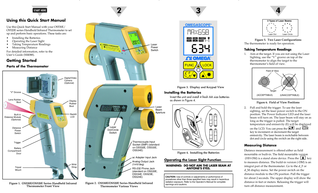
Taking Temperature Readings
1.Aim at the target. If you are not using the Laser Sighting, use the “V” groove on top of the thermometer to align the target to the thermometer’s field of view.
Field of View
“V” Groove
Lens Rubber Boot
Display
Rubber
Boot
Installing the Batteries
Invert the unit and install 4 fresh AA size batteries as shown in Figure 4.
![]() Laser
Laser
Beam
Aperture
Target
(ACCEPTABLE) (UNACCEPTABLE)
Figure 6. Field of View Positions
2. Pull and hold the trigger. To use the laser |
sighting, set the laser power switch to the ON |
Backlit | |
Distance Module | LCD |
(Optional) |
|
Distance
Power
Switch
Trigger
Battery
Compartment
Door
Wrist
TripodStrap
Mount
Figure 1. OS530E/OS520E Series Handheld Infrared
Thermometer Front View
Laser
Dot/Circle
Switch
Thermocouple Input Socket (SMP) (standard on OS532E, OS533E, OS534E)
ac Adapter Input Jack
Analog Output Jack (1mV/deg)
Figure 2. OS530E/OS520E Series Handheld Infrared
Thermometer Various Views
Figure 4. Installing the Batteries
Operating the Laser Sight Function
WARNING: DO NOT AIM THE LASER BEAM AT
ANYONE’S EYES.
CAUTION: Use of controls or adjustments or performance of procedures other than those specified here may result in hazardous radiation exposure. Refer to the Operator’s Manual for complete warnings and cautions.
position. The Power Indicator LED and the laser | |
beam will turn on. The laser beam will stay on as | |
long as the trigger is pulled. The target | |
temperature and emissivity (E) will be displayed | |
on the LCD. You can press the | and C F |
key to increment or decrement the target | |
emissivity. The laser beam is switchable between | |
dot and circle using the switch on the right side. | |
Measuring Distance
Distance measurement is offered either as field mountable or
![]() key to measure distance. The
key to measure distance. The