Omega Engineering WMS-22A manual Transmitter Installation, Operational Checkout

Models: WMS-22 WMS-22A

1 12
Download 12 pages 15.85 Kb
Page 6
Image 6
4.3 Transmitter Installation

4.2 Wind Sensor Installation

Choose the mounting location for the wind sensor and temperature sensor unit which is free from obstructions. Use extreme care to prevent contact with electrical power lines while erecting the unit. A typical installation will position the wind sensor approximately 10 meters above the highest obstacle within a 300 meter radius of the mounting locations. Position the WMS-22 sensor on the end of a 1” diameter TV mast tubing or a 314” Schedule 40 pipe. If the pole is metal it should be well grounded electrically to minimize the probability of any lightning damage. Turn the anemometer on the pole so that the setscrew on the anemometer base is facing True North. Tighten the setscrew to fix the directional orientation.

4.3 Transmitter Installation

Mount the transmitter assembly in a covered location where it can be conveniently connected to its exterior wind sensor. The six-wire cable to the wind sensor may be extended to up to 250 feet in length without degrading the accuracy of its measurements. Orient the sensor so that the setscrew in its base is pointing to North. Use care not to puncture the jacket of the interconnecting cable if staples are used to secure it. The standard wind sensor is supplied with 40 feet of cable. In the event that the interconnecting cable needs to be extended, use good splicing techniques and waterproof the splice if it will be exposed to the weather.

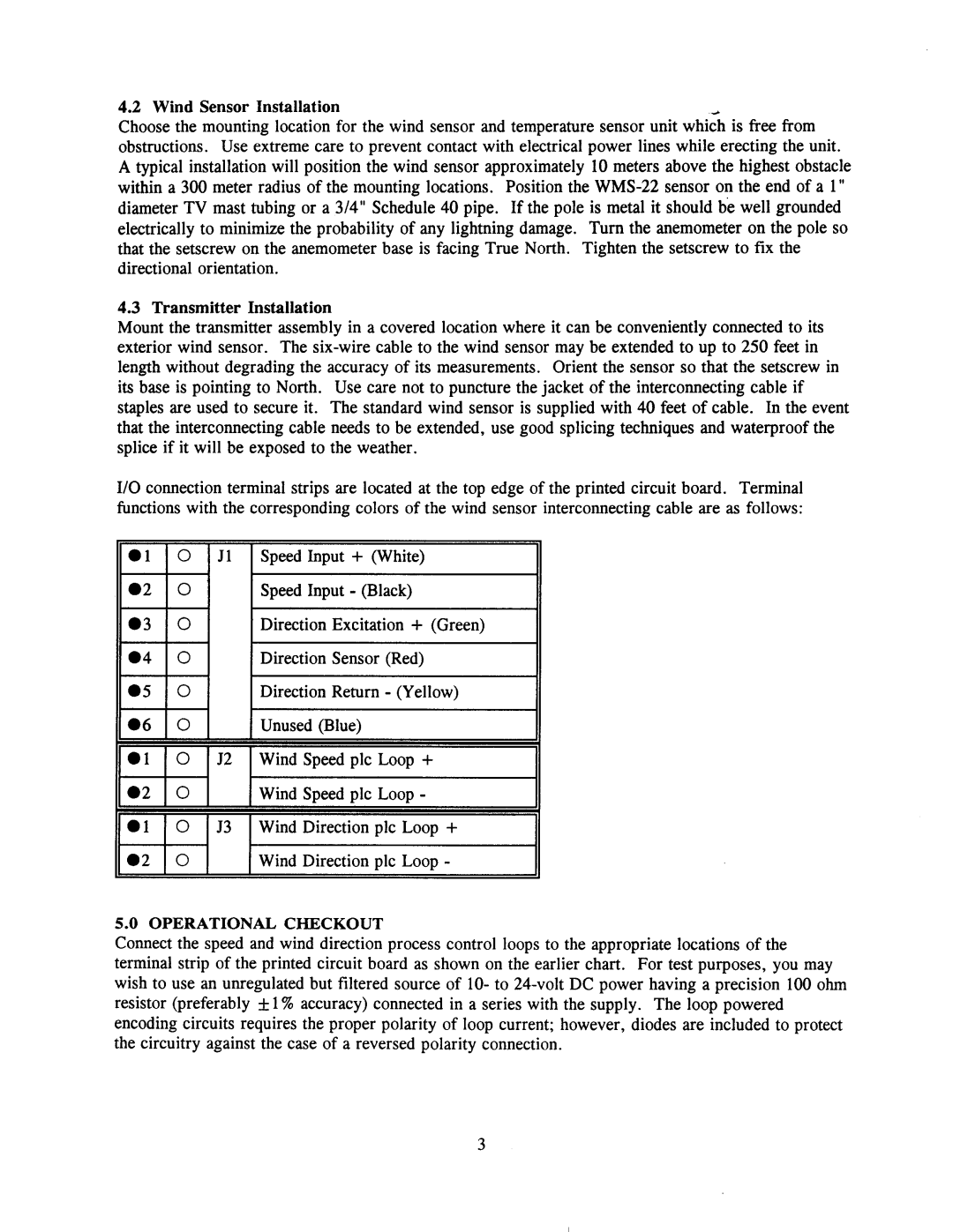
I/O connection terminal strips are located at the top edge of the printed circuit board. Terminal functions with the corresponding colors of the wind sensor interconnecting cable are as follows:

0 1 1 0 1 Jl 1 Speed Input + (White)

2 lo l I Speed Input - (Black)

5 lo l I Direction Return - (Yellow)

06 0

Unused (Blue)

01 0 52 Wind Speed plc Loop +

a2 0Wind Sneed ~lc LOOD -

01 0 53 Wind Direction plc Loop +

a2 0Wind Direction plc Loop -

5.0 OPERATIONAL CHECKOUT

Connect the speed and wind direction process control loops to the appropriate locations of the terminal strip of the printed circuit board as shown on the earlier chart. For test purposes, you may wish to use an unregulated but filtered source of lo- to 24-volt DC power having a precision 100 ohm resistor (preferably f 1% accuracy) connected in a series with the supply. The loop powered encoding circuits requires the proper polarity of loop current; however, diodes are included to protect the circuitry against the case of a reversed polarity connection.

Page 6
Image 6
Omega Engineering WMS-22A manual Transmitter Installation, Operational Checkout