2
2.1 INSTALLING THE DUAL-RELAY OPTION BOARD
To install the
!CAUTION: The meter has no
!IMPORTANT: Disconnect the power from the unit before installing this option board.
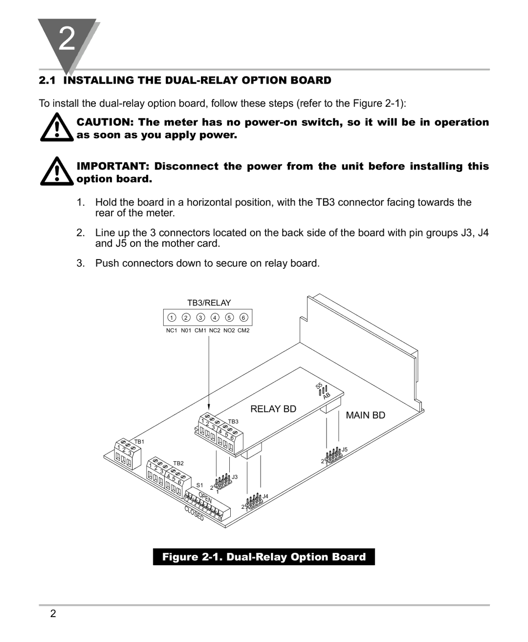
1.Hold the board in a horizontal position, with the TB3 connector facing towards the rear of the meter.
2.Line up the 3 connectors located on the back side of the board with pin groups J3, J4 and J5 on the mother card.
3.Push connectors down to secure on relay board.
TB3/RELAY
1 2 3 4 5 6
NC1 N01 CM1 NC2 NO2 CM2
S5
AB
1 2 3
TB1
RELAY BD
TB3
4 5 6
MAIN BD
1 2 3
1TB2
2 3
4 5 | 6 |
|
|
| S1 | 2 | |
|
| ||
|
|
|
1 |
|
|
|
| O |
|
|
| |
2 |
|
|
|
| P |
|
| ||
| 3 |
|
|
|
| E |
| ||
C | 4 | 5 |
|
| N |
| |||
|
|
| 7 |
|
| ||||
|
|
|
|
| 8 |
| |||
| LO |
|
| 6 |
|
| |||
|
|
| S |
|
|
|
| 9 | |
|
|
|
| E |
|
|
| ||
|
|
|
|
|
| D |
|
|
|
J5
2 1
![]() J3
J3
1
J4
2 1
10
Figure 2-1. Dual-Relay Option Board
2