2

2.3 ELECTRICAL CONNECTION AND SPECIFICATION

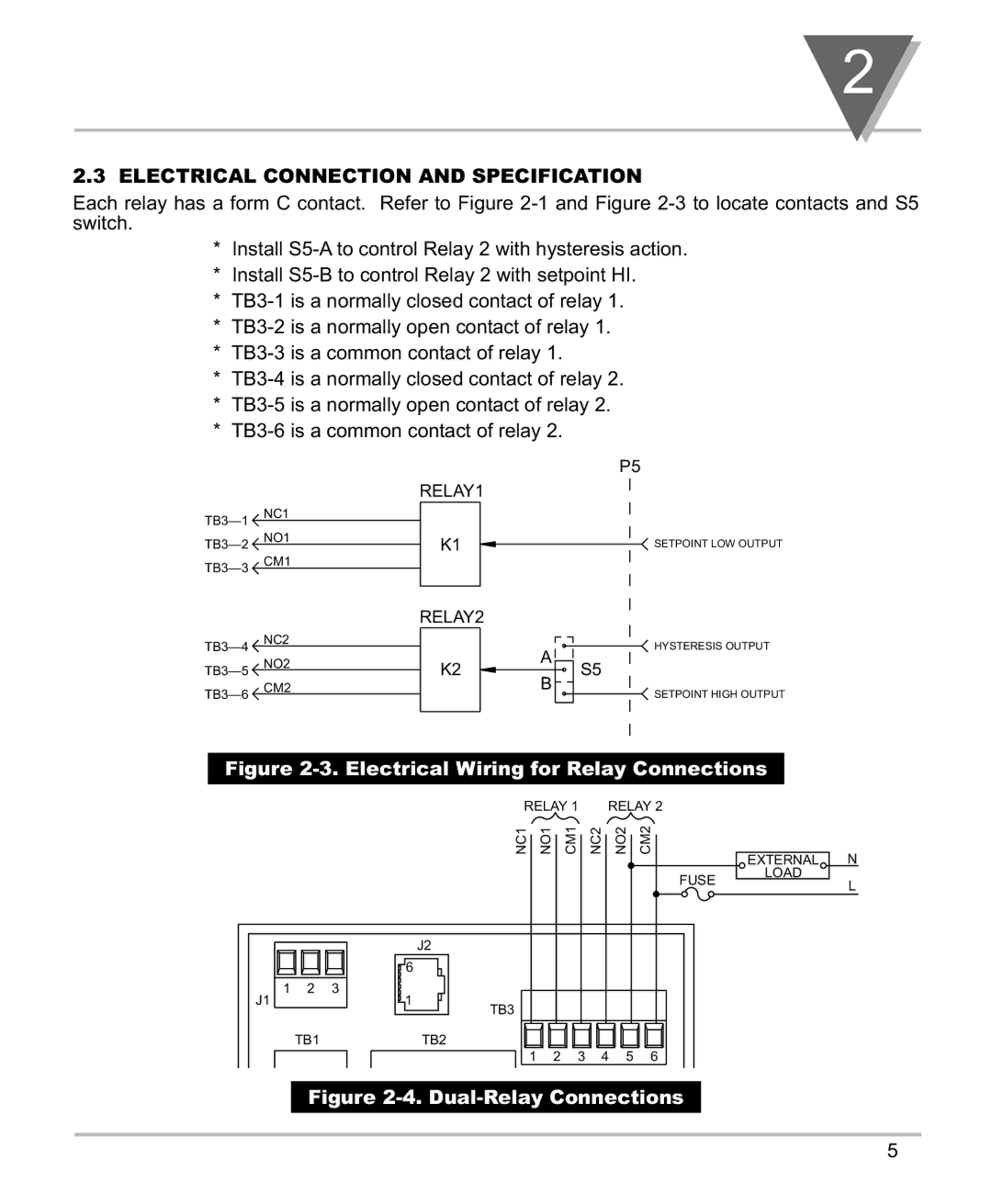
Each relay has a form C contact. Refer to Figure 2-1 and Figure 2-3 to locate contacts and S5 switch.

*Install S5-A to control Relay 2 with hysteresis action.

*Install S5-B to control Relay 2 with setpoint HI.

*TB3-1 is a normally closed contact of relay 1.

*TB3-2 is a normally open contact of relay 1.

*TB3-3 is a common contact of relay 1.

*TB3-4 is a normally closed contact of relay 2.

*TB3-5 is a normally open contact of relay 2.

*TB3-6 is a common contact of relay 2.

NC1

TB3—1 TB3—2 NO1 TB3—3 CM1

NC2

TB3—4 TB3—5 NO2 TB3—6 CM2


P5

RELAY1


K1

SETPOINT LOW OUTPUT

RELAY2


HYSTERESIS OUTPUT

K2

A

S5


B


SETPOINT HIGH OUTPUT

Figure 2-3. Electrical Wiring for Relay Connections

RELAY 1


RELAY 2


NC1

NO1

CM1

NC2

NO2

CM2

N


EXTERNAL

LOAD

FUSEL

J2

6

1 2 3

J11

TB3

TB1TB2

1 2 3 4 5 6

Figure 2-4. Dual-Relay Connections

10-1. Dual-Relay Option Board

5

Page 9
Image 9
Omega Speaker Systems DPF700 manual Electrical Connection and Specification, RELAY2