INSTALLATION
Step Four
OMEGA's
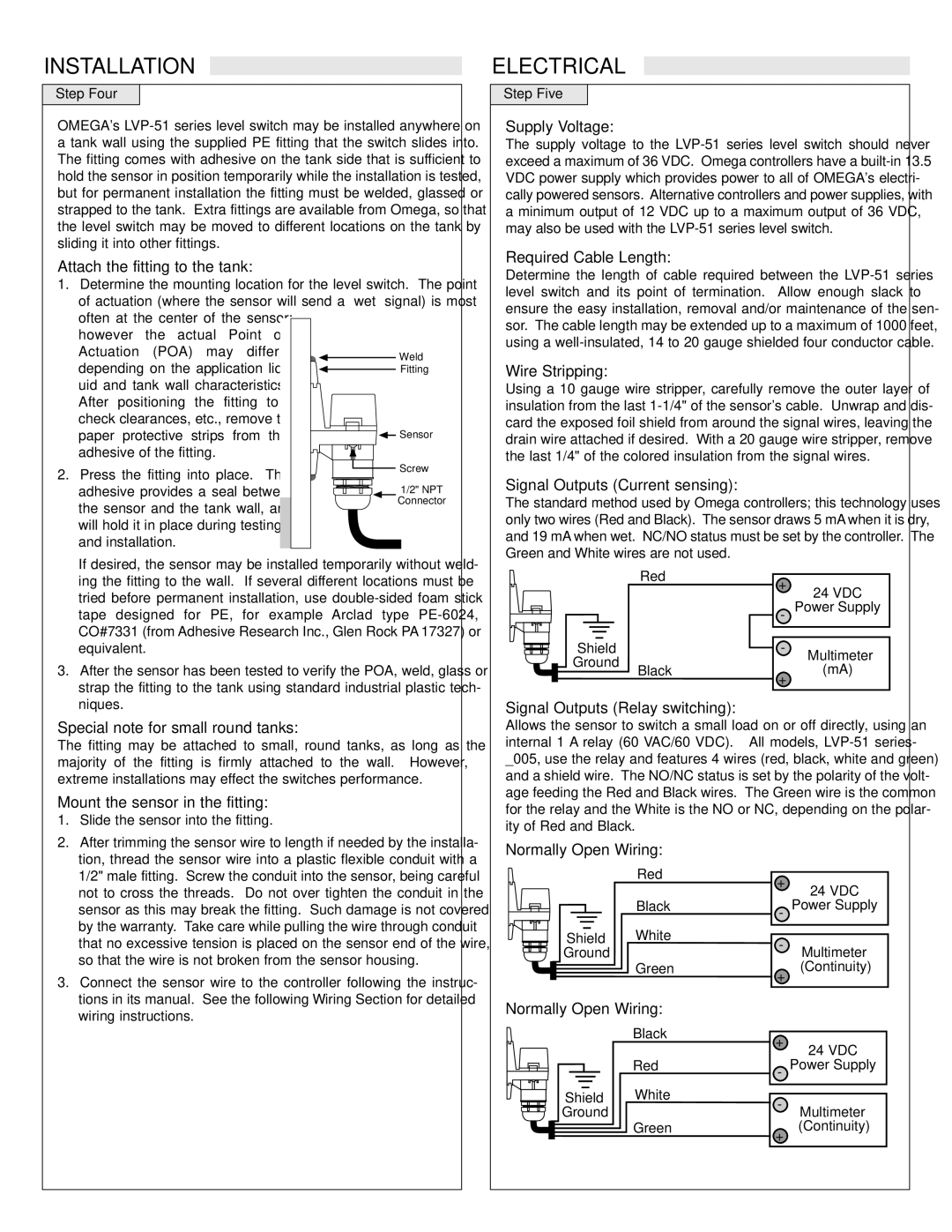
Attach the fitting to the tank:
1.Determine the mounting location for the level switch. The point of actuation (where the sensor will send a “wet” signal) is most
often at the center of the sensor; |
| |
however the actual Point of |
| |
Actuation (POA) may differ | Weld | |
depending on the application liq- | ||
Fitting | ||
uid and tank wall characteristics. |
| |
After positioning the fitting to |
| |
check clearances, etc., remove the |
| |
paper protective strips from the | Sensor | |
adhesive of the fitting. |
| |
2. Press the fitting into place. The | Screw | |
| ||
adhesive provides a seal between | 1/2" NPT | |
the sensor and the tank wall, and | Connector | |
| ||
will hold it in place during testing |
| |
and installation. |
|
ELECTRICAL
Step Five
Supply Voltage:
The supply voltage to the
Required Cable Length:
Determine the length of cable required between the
Wire Stripping:
Using a 10 gauge wire stripper, carefully remove the outer layer of insulation from the last
Signal Outputs (Current sensing):
The standard method used by Omega controllers; this technology uses only two wires (Red and Black). The sensor draws 5 mA when it is dry, and 19 mA when wet. NC/NO status must be set by the controller. The Green and White wires are not used.
If desired, the sensor may be installed temporarily without weld- ing the fitting to the wall. If several different locations must be tried before permanent installation, use
Shield Ground
Red
+
24 VDC
- Power Supply
-
Multimeter
3. After the sensor has been tested to verify the POA, weld, glass or |
strap the fitting to the tank using standard industrial plastic tech- |
Black
+
(mA)
niques. |
Special note for small round tanks:
The fitting may be attached to small, round tanks, as long as the majority of the fitting is firmly attached to the wall. However, extreme installations may effect the switches performance.
Mount the sensor in the fitting:
1. | Slide the sensor into the fitting. |
2. | After trimming the sensor wire to length if needed by the installa- |
Signal Outputs (Relay switching):
Allows the sensor to switch a small load on or off directly, using an internal 1 A relay (60 VAC/60 VDC). All models,
tion, thread the sensor wire into a plastic flexible conduit with a |
1/2" male fitting. Screw the conduit into the sensor, being careful |
not to cross the threads. Do not over tighten the conduit in the |
sensor as this may break the fitting. Such damage is not covered |
by the warranty. Take care while pulling the wire through conduit |
that no excessive tension is placed on the sensor end of the wire, |
so that the wire is not broken from the sensor housing. |
Normally Open Wiring:
| Red |
|
|
| |
| Black |
|
|
|
|
Shield | White | |
Ground |
|
|
+
24 VDC
- Power Supply
-
Multimeter
3. Connect the sensor wire to the controller following the instruc- |
tions in its manual. See the following Wiring Section for detailed |
Green |
+
(Continuity)
wiring instructions. |
Normally Open Wiring:
| Black |
|
|
| |
| Red |
|
|
|
|
Shield | White | |
Ground |
|
|
+
24 VDC
- Power Supply
-
Multimeter
Green |
+
(Continuity)