CALIBRATION
Step Eight
CALIBRATION
Step Nine
After it is installed in place, the
1.Remove the cap from the sensor body by loosening the two screws located below the sensor. Do not remove the screws from the sensor. Insert a small screwdriver into the small slot at the edge of the cap and gently pry upwards.
2.Looking down you will see a small
3.Full state: With ![]()
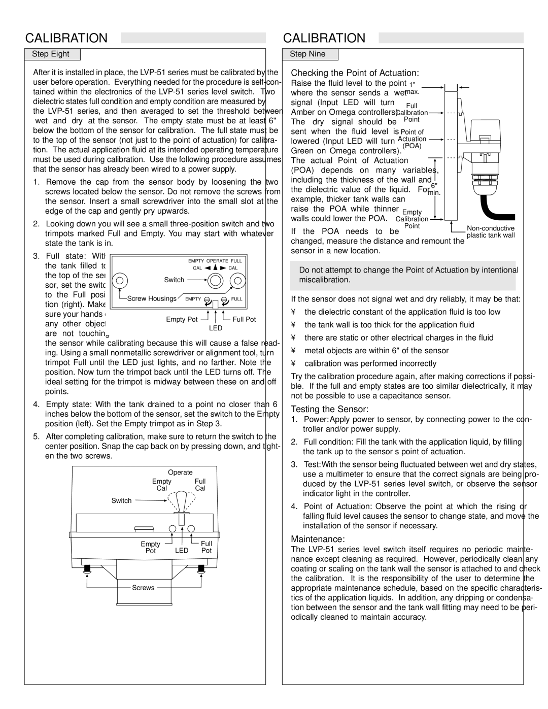
Checking the Point of Actuation:
Raise the fluid level to the point | 1" |
|
|
| ||
where the sensor sends a “wet” |
| max. |
|
|
| |
signal (Input LED will turn |
| Full |
|
|
| |
|
|
|
|
| ||
Amber on Omega controllers). Calibration |
|
| ||||
The “dry” signal should be |
| Point |
|
|
| |
sent when the fluid level is | Point of |
|
|
| ||
lowered (Input LED will turn | Actuation |
|
|
| ||
Green on Omega controllers). | (POA) |
|
|
| ||
|
|
|
|
| ||
The actual Point of Actuation |
|
|
|
| ||
|
|
|
| |||
|
|
|
| |||
(POA) depends on many variables, |
|
|
| |||
including the thickness of the wall and |
|
|
| |||
| 6" | |||||
the dielectric value of the liquid. | For |
| ||||
min. | ||||||
example, thicker tank walls can |
|
| ||||
|
|
|
|
| ||
raise the POA while thinner | Empty |
|
|
| ||
walls could lower the POA. |
|
|
| |||
Calibration |
|
| ||||
Point
If the POA needs to be
changed, measure the distance and remount the sensor in a new location.
the | tank filled to |
| EMPTY OPERATE FULL | ||
| CAL | CAL | |||
the top of the sen- | Switch |
|
| ||
sor, set the switch |
|
| |||
|
|
| |||
to the Full posi- | Screw Housings | EMPTY | FULL | ||
tion (right). Make | |||||
|
|
| |||
sure your hands or | Empty Pot | Full Pot | |||
any | other objects | ||||
|
| LED | |||
are | not touching |
|
| ||
|
|
| |||
the sensor while calibrating because this will cause a false read- ing. Using a small nonmetallic screwdriver or alignment tool, turn trimpot Full until the LED just lights, and no farther. Note the position. Now turn the trimpot back until the LED turns off. The ideal setting for the trimpot is midway between these on and off points.
4.Empty state: With the tank drained to a point no closer than 6 inches below the bottom of the sensor, set the switch to the Empty position (left). Set the Empty trimpot as in Step 3.
5.After completing calibration, make sure to return the switch to the center position. Snap the cap back on by pressing down, and tight- en the two screws.
Operate
Empty Full
Cal Cal
Switch
Empty |
| Full |
Pot | LED | Pot |
![]() Screws
Screws ![]()
Do not attempt to change the Point of Actuation by intentional miscalibration.
If the sensor does not signal wet and dry reliably, it may be that:
•the dielectric constant of the application fluid is too low
•the tank wall is too thick for the application fluid
•there are static or other electrical charges in the fluid
•metal objects are within 6" of the sensor
•calibration was performed incorrectly
Try the calibration procedure again, after making corrections if possi- ble. If the full and empty states are too similar dielectrically, it may not be possible to use a capacitance sensor.
Testing the Sensor:
1.Power: Apply power to sensor, by connecting power to the con- troller and/or power supply.
2.Full condition: Fill the tank with the application liquid, by filling the tank up to the sensor’s point of actuation.
3.Test: With the sensor being fluctuated between wet and dry states, use a multimeter to ensure that the correct signals are being pro- duced by the
4.Point of Actuation: Observe the point at which the rising or falling fluid level causes the sensor to change state, and move the installation of the sensor if necessary.
Maintenance:
The