WIRING
Step Six
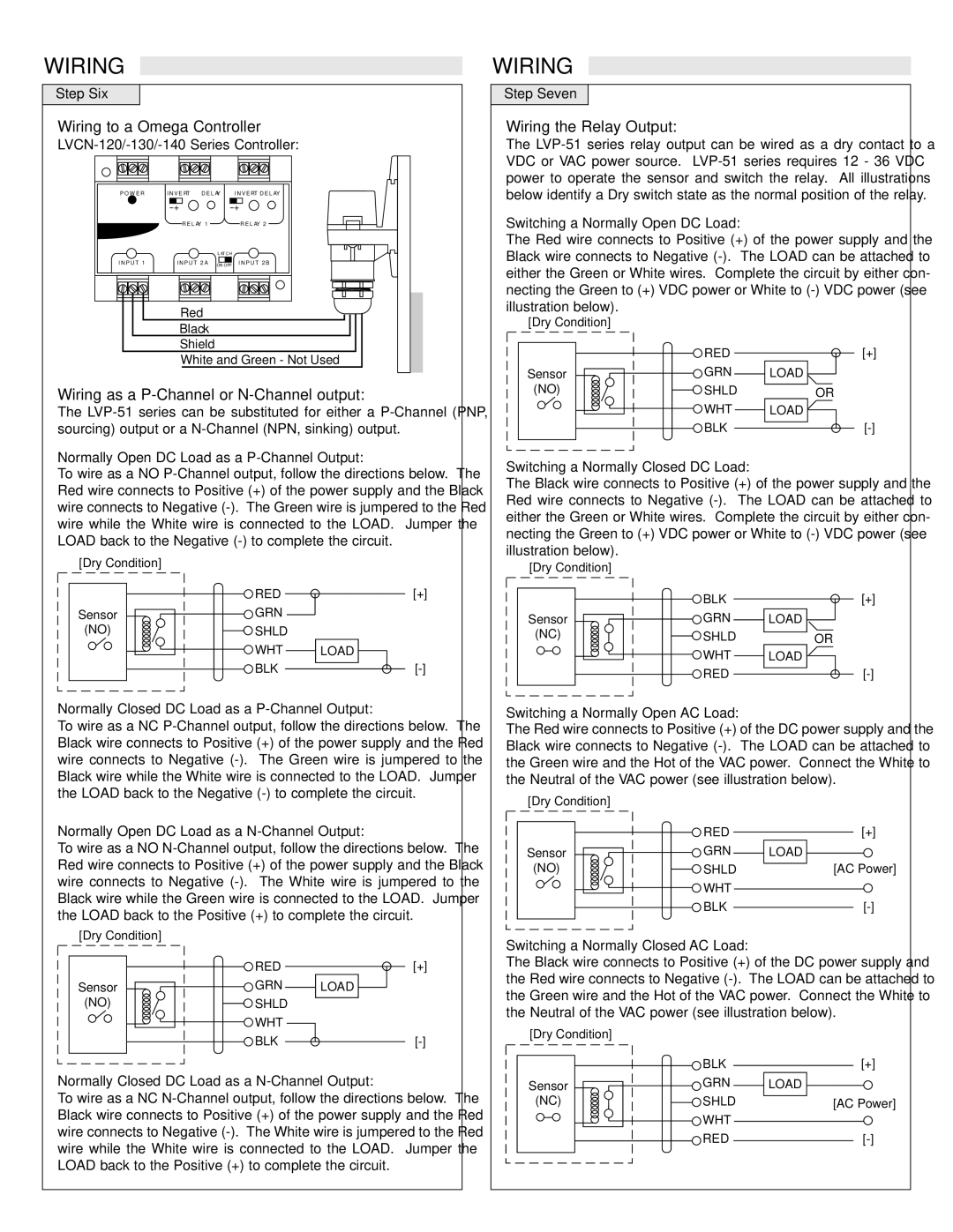
Wiring to a Omega Controller
P O W E R | I N V E RT | D E L AY | I N V E RT D E L AY | |
|
| |||
| R E L AY 1 |
| R E L AY 2 | |
|
|
| L AT C H |
|
I N P U T 1 | I N P U T 2 A | ON OFF | I N P U T 2 B | |
| Red |
|
| |
WIRING
Step Seven
Wiring the Relay Output:
The
Switching a Normally Open DC Load:
The Red wire connects to Positive (+) of the power supply and the Black wire connects to Negative
Black |
Shield |
White and Green - Not Used |
Wiring as a P-Channel or N-Channel output:
The
[Dry Condition] |
Sensor |
(NO) |
RED
GRN
SHLD
WHT
BLK
[+]
LOAD
OR
LOAD
Normally Open DC Load as a P-Channel Output:
To wire as a NO
Switching a Normally Closed DC Load:
The Black wire connects to Positive (+) of the power supply and the Red wire connects to Negative
[Dry Condition] |
Sensor |
(NO) |
RED
GRN
SHLD
WHT
BLK
[+]
LOAD
[Dry Condition]
| BLK | [+] |
Sensor | GRN | LOAD |
(NC) | SHLD | OR |
| WHT | LOAD |
| RED |
Normally Closed DC Load as a P-Channel Output:
To wire as a NC
Switching a Normally Open AC Load:
The Red wire connects to Positive (+) of the DC power supply and the Black wire connects to Negative
Normally Open DC Load as a N-Channel Output:
To wire as a NO
[Dry Condition] |
Sensor |
(NO) |
RED
GRN
SHLD
WHT
BLK
[+]
LOAD
[AC Power]
[Dry Condition] |
Sensor |
(NO) |
RED
GRN
SHLD
WHT
[+]
LOAD
Switching a Normally Closed AC Load:
The Black wire connects to Positive (+) of the DC power supply and the Red wire connects to Negative
BLK
[Dry Condition]
BLK
[+]
Normally Closed DC Load as a N-Channel Output:
To wire as a NC
Sensor
(NC)
GRN
SHLD
WHT
RED
LOAD
[AC Power]