C. Hub Ring Out (RJ45) to distant hub Ring In (RJ45)
Application C shows the Ring Out of one hub connected to the Ring In of another hub via a pair of OmniHawk™ converters. Note that the cable from the second OmniHawk™ to the Ring In is a crossed cable.
D. Distant Lobe Extension
Application D shows a distant hub in lobe extension via a pair of OmniHawk™ converters. In this configuration a standard
E. Other Applications
The above examples show the most common applications of the OmniHawk™. Your network may require an application not listed here. The configuration you need will be supported by the OmniHawk™ as long as the correct cable is used. The fiber optic cables will always be the same. The table below will guide you in selecting the proper copper cables, media filters, and connector adapters.
OST PART # CONNECT FROM CONNECT TO |
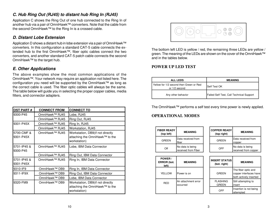
The bottom left LED is yellow / red, the remaining three LEDs are yellow / green. The meaning of the LEDs are shown on the cover of the OmniHawk™ and in the tables below.
POWER UP LED TEST
ALL LEDS | MEANING | |
Yellow for 1/2 second then Green or Red | Self Test OK | |
or 1/2 second | ||
| ||
Any other behavior | Failed Self Test, Call Technical Support | |
|
|
The OmniHawk™ performs a self test every time power is newly applied.
OmniHawk™ RJ45 | Lobe, RJ45 | |
| OmniHawk™ RJ45 | Ring Out, RJ45 |
OmniHawk™ RJ45 | Ring In, RJ45 | |
| OmniHawk™ RJ45 | Workstation, RJ45 |
OPERATIONAL MODES
FIBER READY
OmniHawk™ RJ45 Workstation, DB9(if not directly | |
attaching the OmniHawk™ to the |
(top left)
MEANING
MEANING |
(top right) |
workstation) |
GREEN
Data received from fiber
Data received from |
GREEN |
copper |
OmniHawk™ RJ45 | Lobe, IBM Data Connector | |
|
| |
| OmniHawk™ RJ45 | Ring Out, IBM Data Connector |
Off
No data is being received from Fiber
No data is being |
OFF |
received from copper |
OmniHawk™ RJ45 | Ring In, IBM Data Connector | |
|
| |
|
|
|
OmniHawk™ DB9 | Ring In, IBM Data Connector | |
OmniHawk™ DB9 | Ring Out, IBM Data Connector | |
| OmniHawk™ DB9 | Lobe, IBM Data Connector |
OmniHawk™ DB9 | Workstati on, DB9(if not directly | |
|
| attaching the OmniHawk™ to the |
|
| workstation) |
POWER / |
| |
ERROR (bot. | MEANING | |
left) |
| |
YELLOW | Power is on | |
|
| |
RED | An attachment error | |
occurred | ||
|
INSERT STATUS | MEANING | |
(bot. right) | ||
| ||
|
| |
| The fiber optic and | |
GREEN | copper interfaces have | |
| both actively inserted | |
FLASHING | Still attempting to | |
GREEN | insert | |
OFF | Insertion is not being | |
attempted | ||
|
10 | 3 |