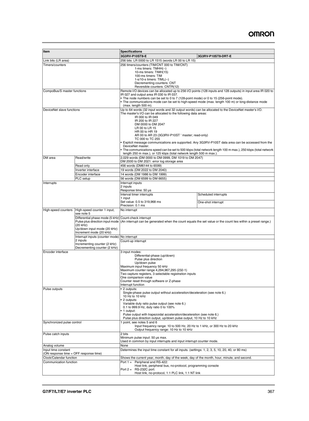
Item |
| Specifications |
|
|
|
| |
Link bits (LR area) |
| 256 bits: LR 0000 to LR 1515 (words LR 00 to LR 15) |
|
|
|
|
|
Timers/counters |
| 256 timers/counters (TIM/CNT 000 to TIM/CNT) |
|
|
|
| |
|
|
| |
|
|
| |
|
|
| |
|
| Decrementing counters: CNT |
|
|
| Reversible counters: CNTR(12) |
|
CompoBus/S master functions | Remote I/O devices can be allocated up to 256 I/O points (128 inputs and 128 outputs) in input area IR 020 to | ||
|
| IR 027 and output area IR 030 to IR 037. |
|
|
| • The node numbers can be set to 0 to 7 | |
|
| • The communications mode can be set to | |
|
| (max. length 500 m). |
|
|
| ||
DeviceNet slave functions | Up to 64 words (32 input words and 32 output words) can be allocated to the DeviceNet master's I/O. | ||
|
| The master's I/O can be allocated to the following data areas: | |
|
| IR 000 to IR 049 |
|
|
| IR 200 to IR 227 |
|
|
| DM 0000 to DM 2047 |
|
|
| LR 00 to LR 15 |
|
|
| HR 00 to HR 19 |
|
|
| AR 00 to AR 23 | |
|
| TC 000 to TC 255 |
|
|
| • Explicit message communications are supported. Any | |
|
| DeviceNet master. |
|
|
| • The communications speed can be set to 500 kbps (total network length 100 m max.), 250 kbps (total network | |
|
| length 250 m max.), or 125 kbps (total network length 500 m max.). | |
DM area | Read/write | 2,029 words (DM 0000 to DM 0999, DM 1019 to DM 2047) | |
|
| DM 2000 to DM 2021: error log storage area |
|
|
|
|
|
| Read only | 456 words (DM6144 to 6599) |
|
| Inverter interface | 19 words (DM 2022 to DM 2040) |
|
| Encoder interface | 14 words (DM 1986 to DM 1999) |
|
|
|
|
|
| PLC setup | 56 words (DM 6599 to DM 6655) |
|
Interrupts |
| Interrupt inputs |
|
|
| 2 inputs |
|
|
| Response time: 50 µs |
|
|
| Interval timer interrupts | Scheduled interrupts |
|
| 1 input |
|
|
| Set value: 0.5 to 319,968 ms | |
|
| Precision: 0.1 ms |
|
|
|
|
|
No interrupt |
| ||
| see note 5 |
|
|
| Differential phase mode (5 kHz) |
| |
| Pulse plus direction input mode | (An interrupt can be generated when the count equals the set value or the count lies within a preset range.) | |
| (20 kHz) |
|
|
| Up/down input mode (20 kHz) |
|
|
| Increment mode (20 kHz) |
|
|
| Interrupt inputs (counter mode) | No interrupt |
|
| 2 inputs |
| |
| Incrementing counter (2 kHz) |
|
|
| Decrementing counter (2 kHz) |
|
|
Encoder interface |
| 3 input modes: |
|
|
|
| |
|
| Pulse plus direction |
|
|
| Up/down pulse |
|
|
| Maximum input frequency 50 kHz |
|
|
| Maximum counter range 4,294,967,295 |
|
|
| Two capture registers, 3 selectable registration inputs |
|
|
| One comparison value |
|
|
| Counter reset through software or |
|
|
| Interrupt function |
|
|
|
|
|
Pulse outputs |
| • 2 outputs: |
|
|
| ||
|
| 10 Hz to 10 kHz |
|
|
| • 2 outputs: |
|
|
| Variable duty ratio pulse output (see note 6.) |
|
|
| 0.1 to 999.9 Hz, duty ratio 0 to 100% |
|
|
| • 1 output: |
|
|
| Pulse output with trapezoidal acceleration/deceleration (see note 6.) | |
|
| Pulse plus direction output, up/down pulse output, 10 Hz to 10 kHz | |
|
|
| |
Synchronized pulse control | 1 point, see notes 5 and 6 |
| |
|
| Input frequency range: 10 to 500 Hz, 20 Hz to 1 kHz, or 300 Hz to 20 kHz | |
|
| Output frequency range: 10 Hz to 10 kHz |
|
|
|
|
|
Pulse catch inputs |
| 2 bits |
|
|
| Minimum pulse input: 50 µs max. |
|
|
| Used in common by input interrupts and input interrupt counter mode. | |
|
|
|
|
Analog volume |
| None |
|
Input time constant |
| Determines the input time constant for all inputs. (settings: 1, 2, 3, 5, 10, 20, 40, or 80 ms) | |
(ON response time = OFF response time) |
|
| |
|
| ||
Clock/Calendar function | Shows the current year, month, day of the week, day of the month, hour, minute, and second. | ||
Communication function | Port 1 = Peripheral and |
| |
|
| Host link, peripheral bus, | |
|
| Port 2 = |
|
|
| Host link, | |
G7/F7/L7/E7 inverter PLC | 367 |