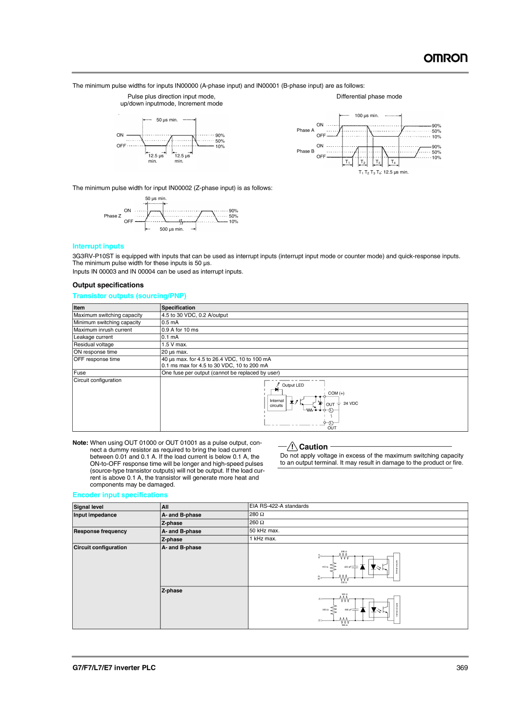
The minimum pulse widths for inputs IN00000
Pulse plus direction input mode,
up/down inputmode, Increment mode
50 µs min.
ON |
|
|
|
|
|
|
|
| 90% | ||
OFF |
|
|
| 50% | |
|
|
| 10% | ||
|
| 12.5 µs | 12.5 µs |
|
|
|
|
|
| ||
|
|
|
| ||
|
| min. | min. |
|
|
| Differential phase mode | ||
|
|
| |
|
| 100 µs min. |
|
ON | 90% | ||
Phase A | 50% | ||
OFF | 10% | ||
ON |
|
| 90% |
Phase B |
|
| 50% |
OFF |
|
| 10% |
T1 | T2 | T3 | T4 |
| T1 T2 T3 T4: 12.5 µs min. | ||
The minimum pulse width for input IN00002
ON | 50 | µs | min. |
90% | |||
Phase Z | 50% | ||
OFF | 10% | ||
500 µs min.
Interrupt inputs
Inputs IN 00003 and IN 00004 can be used as interrupt inputs.
Output specifications
Transistor outputs (sourcing/PNP)
Item | Specification |
|
|
|
| ||||
Maximum switching capacity | 4.5 to 30 VDC, 0.2 A/output |
|
|
|
| ||||
|
|
|
|
|
|
|
|
|
|
Minimum switching capacity | 0.5 mA |
|
|
|
| ||||
Maximum inrush current | 0.9 A for 10 ms |
|
|
|
| ||||
|
|
|
|
|
|
|
|
|
|
Leakage current | 0.1 mA |
|
|
|
| ||||
|
|
|
|
|
|
|
|
|
|
Residual voltage | 1.5 V max. |
|
|
|
| ||||
ON response time | 20 µs max. |
|
|
|
| ||||
|
|
|
|
|
|
|
|
|
|
OFF response time | 40 µs max. for 4.5 to 26.4 VDC, 10 to 100 mA |
|
|
|
| ||||
| 0.1 ms max for 4.5 to 30 VDC, 10 to 200 mA |
|
|
|
| ||||
Fuse | One fuse per output (cannot be replaced by user) |
|
|
|
| ||||
|
|
|
|
|
|
|
|
|
|
Circuit configuration |
|
|
|
|
|
|
|
|
|
|
|
| Output LED |
|
|
|
|
| |
|
|
|
|
|
|
|
| ||
|
|
|
|
|
|
| COM (+ | ) | |
|
|
|
|
|
|
|
|
|
|
|
| Internal |
|
|
|
| 24 VDC | ||
|
|
|
| OUT |
| ||||
|
| circuits |
|
| |||||
|
|
|
|
|
|
| OUT | ||
|
|
|
|
|
|
|
|
|
|
Note: When using OUT 01000 or OUT 01001 as a pulse output, con- nect a dummy resistor as required to bring the load current between 0.01 and 0.1 A. If the load current is below 0.1 A, the
!Caution
Do not apply voltage in excess of the maximum switching capacity to an output terminal. It may result in damage to the product or fire.
Encoder input specifications
Signal level | All | EIA |
|
|
Input impedance | A- and | 280 Ω |
|
|
| 260 Ω |
|
| |
Response frequency | A- and | 50 kHz max. |
|
|
| 1 kHz max. |
|
| |
Circuit configuration | A- and |
| 330 Ω |
|
|
|
|
| |
|
| A |
|
|
|
| B |
|
|
|
| 410 Ω | 220 pF | circuits |
|
| Intrnal | ||
|
|
|
| |
|
| /A |
|
|
|
| /B |
|
|
|
|
| 330 Ω |
|
|
| 180 Ω |
| |
|
|
|
| |
|
| Z |
|
|
|
| 560 Ω | 680 pF | circuits |
|
| Intrnal | ||
|
|
|
| |
|
| /Z |
|
|
|
|
| 180 Ω |
|
G7/F7/L7/E7 inverter PLC | 369 |