Operation
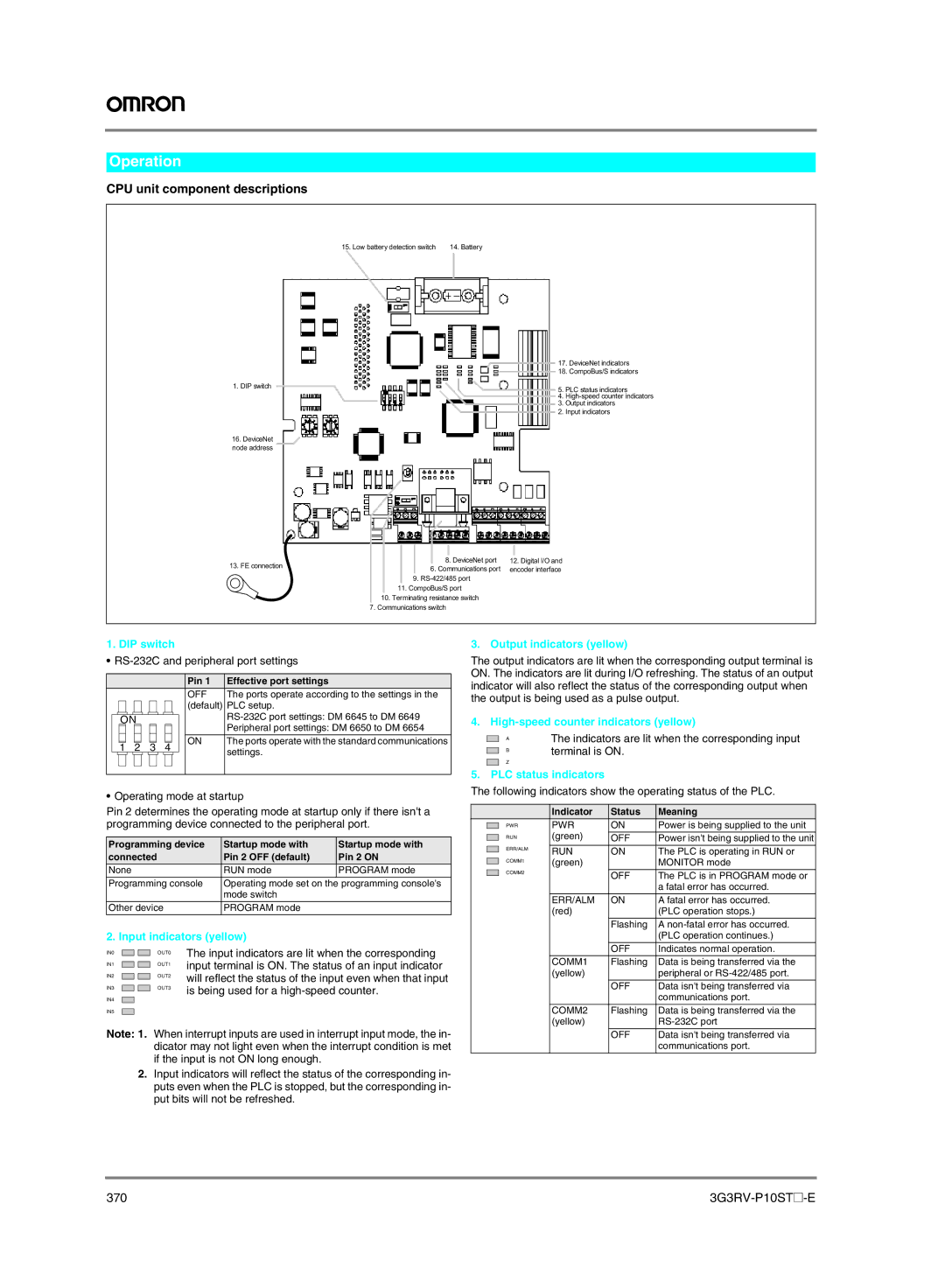
CPU unit component descriptions
15. Low battery detection switch | 14. Battery |
| 17. | DeviceNet indicators | |
| 18. | CompoBus/S indicators | |
1. DIP switch | 5. | PLC status indicators | |
| |||
| 4. | ||
| 3. | Output indicators | |
| 2. | Input indicators | |
16.DeviceNet node address
13. FE connection |
| 8. DeviceNet port | 12. Digital I/O and |
| 6. Communications port | encoder interface | |
|
| ||
|
| 9. |
|
| 11. CompoBus/S port |
| |
| 10. Terminating resistance switch |
| |
| 7. Communications switch |
| |
1. DIP switch
•RS-232C and peripheral port settings
|
|
|
|
|
|
|
|
|
|
| Pin 1 | Effective port settings |
|
|
|
|
|
|
|
|
|
|
| OFF | The ports operate according to the settings in the |
|
|
|
|
|
|
|
|
|
|
| (default) | PLC setup. |
|
|
|
|
|
|
|
|
|
|
| ||
|
| ON |
|
|
|
|
|
|
| |||
|
|
|
|
|
|
|
|
|
|
|
| Peripheral port settings: DM 6650 to DM 6654 |
|
|
|
|
|
|
|
|
|
|
|
|
|
|
|
|
|
|
|
|
|
|
|
| ON | The ports operate with the standard communications |
|
|
|
|
|
|
|
|
|
|
| ||
| 1 | 2 | 3 | 4 |
|
|
| settings. | ||||
|
|
|
|
|
|
|
|
|
|
|
| |
|
|
|
|
|
|
|
|
|
|
|
|
|
|
|
|
|
|
|
|
|
|
|
|
|
|
•Operating mode at startup
Pin 2 determines the operating mode at startup only if there isn't a programming device connected to the peripheral port.
Programming device | Startup mode with | Startup mode with |
connected | Pin 2 OFF (default) | Pin 2 ON |
None | RUN mode | PROGRAM mode |
Programming console | Operating mode set on the programming console's | |
| mode switch |
|
Other device | PROGRAM mode |
|
2. Input indicators (yellow)
IN0 |
|
|
| OUT0 | The input indicators are lit when the corresponding |
IN1 |
|
|
| OUT1 | input terminal is ON. The status of an input indicator |
|
|
| |||
IN2 |
|
|
| OUT2 | will reflect the status of the input even when that input |
|
|
| |||
IN3 |
|
|
| OUT3 | is being used for a |
|
| ||||
IN4 |
|
|
|
| |
|
|
|
|
| |
IN5 |
|
|
|
|
|
|
|
|
|
Note: 1. When interrupt inputs are used in interrupt input mode, the in- dicator may not light even when the interrupt condition is met if the input is not ON long enough.
2.Input indicators will reflect the status of the corresponding in- puts even when the PLC is stopped, but the corresponding in- put bits will not be refreshed.
3. Output indicators (yellow)
The output indicators are lit when the corresponding output terminal is ON. The indicators are lit during I/O refreshing. The status of an output indicator will also reflect the status of the corresponding output when the output is being used as a pulse output.
4.
|
| A | The indicators are lit when the corresponding input |
|
| ||
|
| B | terminal is ON. |
|
| ||
|
| Z |
|
|
|
| |
5. PLC status indicators | |||
The following indicators show the operating status of the PLC.
|
|
| Indicator | Status | Meaning |
|
| PWR | PWR | ON | Power is being supplied to the unit |
|
| ||||
|
|
| (green) |
|
|
|
| RUN | OFF | Power isn't being supplied to the unit | |
|
|
| |||
|
| ERR/ALM | RUN | ON | The PLC is operating in RUN or |
|
|
| |||
|
| COMM1 | (green) |
| MONITOR mode |
|
| COMM2 |
|
|
|
|
|
| OFF | The PLC is in PROGRAM mode or | |
|
|
|
| ||
|
|
|
|
| a fatal error has occurred. |
|
|
| ERR/ALM | ON | A fatal error has occurred. |
|
|
| (red) |
| (PLC operation stops.) |
|
|
|
| Flashing | A |
|
|
|
|
| (PLC operation continues.) |
|
|
|
|
|
|
|
|
|
| OFF | Indicates normal operation. |
|
|
| COMM1 | Flashing | Data is being transferred via the |
|
|
| (yellow) |
| peripheral or |
|
|
|
|
|
|
|
|
|
| OFF | Data isn't being transferred via |
|
|
|
|
| communications port. |
|
|
| COMM2 | Flashing | Data is being transferred via the |
|
|
| (yellow) |
| |
|
|
|
| OFF | Data isn't being transferred via |
|
|
|
|
| communications port. |
|
|
|
|
|
|
370 |