Figure 2. To adjust the latitude angle of the equatorial mount, loosen one of the two latitude adjustment T-bolts, then tighten the other.
assembly from its housing for any reason, or the product war- ranty and return policy will be voided.
1.Lay the equatorial mount on its side. Attach the tripod legs one at a time to the mount using the screws installed in the tops of the tripod legs. Remove the screw from the leg, line up the holes in the top of the leg with the holes in the base of the mount, and reinstall the screw so it passes through the leg and the mount. Tighten the wingnuts only
2.Tighten the leg lock knobs at the base of the tripod legs. For now, keep the legs at their shortest (fully retracted) length; you can extend them to a more desirable length later, after the scope is completely assembled.
3.With the tripod legs now attached to the equatorial mount, stand the tripod upright (be careful!) and spread the legs apart enough to connect each end of the accessory tray bracket to the attachment point on each leg. Use the screw that comes installed in each attachment point to do this. First remove the screw using the supplied screwdriver, then line up one of the ends of the bracket with the attachment point and reinstall the screw. Make sure the accessory tray bracket is oriented so that the ribs in its plastic molding face downward.
4.Now, with the accessory tray bracket attached, spread the tripod legs apart as far as they will go, until the bracket is taut. Attach the accessory tray to the bracket with the three wing-
5.Next, tighten the wingnuts at the top of the tripod legs, so the legs are securely fastened to the equatorial mount. Use the larger wrench and your fingers to do this.
6.Orient the equatorial mount as it appears in Figure 1, at a latitude of about 40°, i.e., so the pointer next to the latitude scale is pointing to the line at “40”. To do this, loosen one of the latitude adjusting
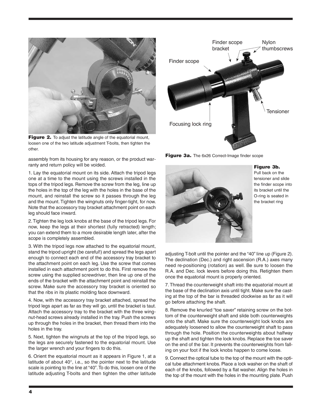
Finder scope | Nylon |
bracket | thumbscrews |
Finder scope
![]() Tensioner
Tensioner
Focusing lock ring
Figure 3a. The 6x26 Correct-Image finder scope
Figure 3b.
Pull back on the tensioner and slide the finder scope into its bracket until the O-ring is seated in the bracket ring
adjusting T-bolt until the pointer and the “40” line up (Figure 2). The declination (Dec.) and right ascension (R.A.) axes many need re-positioning (rotation) as well. Be sure to loosen the R.A. and Dec. lock levers before doing this. Retighten them once the equatorial mount is properly oriented.
7.Thread the counterweight shaft into the equatorial mount at the base of the declination axis until tight. Make sure the cast- ing at the top of the bar is threaded clockwise as far as it will go before attaching the shaft.
8.Remove the knurled “toe saver” retaining screw on the bot- tom of the counterweight shaft and slide both counterweights onto the shaft. Make sure the counterweight lock knobs are adequately loosened to allow the counterweight shaft to pass through the hole. Position the counterweights about halfway up the shaft and tighten the lock knobs. Replace the toe saver on the end of the bar. It prevents the counterweights from fall- ing on your foot if the lock knobs happen to come loose.
9.Connect the optical tube to the top of the mount with the opti- cal tube attachment knobs. Place a lock washer on the shaft of each of the knobs, followed by a flat washer. Align the holes in the top of the mount with the holes in the mounting plate. Push
4