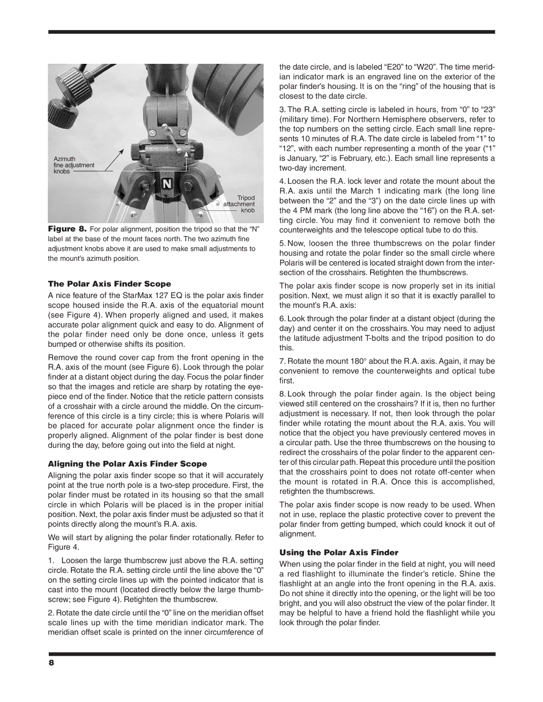
Azimuth
fine adjustment knobs
Tripod attachment knob
Figure 8. For polar alignment, position the tripod so that the “N” label at the base of the mount faces north. The two azimuth fine adjustment knobs above it are used to make small adjustments to the mount’s azimuth position.
The Polar Axis Finder Scope
A nice feature of the StarMax 127 EQ is the polar axis finder scope housed inside the R.A. axis of the equatorial mount (see Figure 4). When properly aligned and used, it makes accurate polar alignment quick and easy to do. Alignment of the polar finder need only be done once, unless it gets bumped or otherwise shifts its position.
Remove the round cover cap from the front opening in the R.A. axis of the mount (see Figure 6). Look through the polar finder at a distant object during the day. Focus the polar finder so that the images and reticle are sharp by rotating the eye- piece end of the finder. Notice that the reticle pattern consists of a crosshair with a circle around the middle. On the circum- ference of this circle is a tiny circle; this is where Polaris will be placed for accurate polar alignment once the finder is properly aligned. Alignment of the polar finder is best done during the day, before going out into the field at night.
Aligning the Polar Axis Finder Scope
Aligning the polar axis finder scope so that it will accurately point at the true north pole is a
We will start by aligning the polar finder rotationally. Refer to Figure 4.
1.Loosen the large thumbscrew just above the R.A. setting circle. Rotate the R.A. setting circle until the line above the “0” on the setting circle lines up with the pointed indicator that is cast into the mount (located directly below the large thumb- screw; see Figure 4). Retighten the thumbscrew.
2.Rotate the date circle until the “0” line on the meridian offset scale lines up with the time meridian indicator mark. The meridian offset scale is printed on the inner circumference of
the date circle, and is labeled “E20” to “W20”. The time merid- ian indicator mark is an engraved line on the exterior of the polar finder’s housing. It is on the “ring” of the housing that is closest to the date circle.
3.The R.A. setting circle is labeled in hours, from “0” to “23” (military time). For Northern Hemisphere observers, refer to the top numbers on the setting circle. Each small line repre- sents 10 minutes of R.A. The date circle is labeled from “1” to “12”, with each number representing a month of the year (“1” is January, “2” is February, etc.). Each small line represents a
4.Loosen the R.A. lock lever and rotate the mount about the R.A. axis until the March 1 indicating mark (the long line between the “2” and the “3”) on the date circle lines up with the 4 PM mark (the long line above the “16”) on the R.A. set- ting circle. You may find it convenient to remove both the counterweights and the telescope optical tube to do this.
5.Now, loosen the three thumbscrews on the polar finder housing and rotate the polar finder so the small circle where Polaris will be centered is located straight down from the inter- section of the crosshairs. Retighten the thumbscrews.
The polar axis finder scope is now properly set in its initial position. Next, we must align it so that it is exactly parallel to the mount’s R.A. axis:
6.Look through the polar finder at a distant object (during the day) and center it on the crosshairs. You may need to adjust the latitude adjustment
7.Rotate the mount 180° about the R.A. axis. Again, it may be convenient to remove the counterweights and optical tube first.
8.Look through the polar finder again. Is the object being viewed still centered on the crosshairs? If it is, then no further adjustment is necessary. If not, then look through the polar finder while rotating the mount about the R.A. axis. You will notice that the object you have previously centered moves in a circular path. Use the three thumbscrews on the housing to redirect the crosshairs of the polar finder to the apparent cen- ter of this circular path. Repeat this procedure until the position that the crosshairs point to does not rotate
The polar axis finder scope is now ready to be used. When not in use, replace the plastic protective cover to prevent the polar finder from getting bumped, which could knock it out of alignment.
Using the Polar Axis Finder
When using the polar finder in the field at night, you will need a red flashlight to illuminate the finder’s reticle. Shine the flashlight at an angle into the front opening in the R.A. axis. Do not shine it directly into the opening, or the light will be too bright, and you will also obstruct the view of the polar finder. It may be helpful to have a friend hold the flashlight while you look through the polar finder.
8