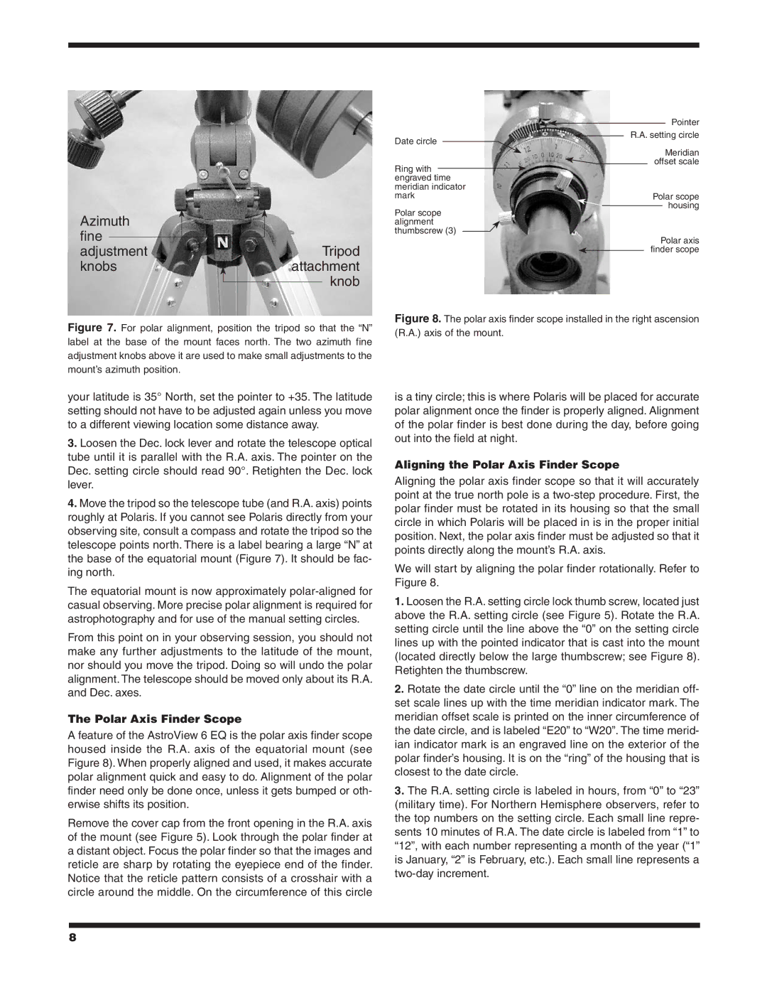
Date circle
Pointer R.A. setting circle
Ring with engraved time
Meridian offset scale
meridian indicator
markPolar scope
Azimuth |
fine |
Polar scope alignment thumbscrew (3)
housing
adjustment |
| Tripod |
knobs | attachment | |
|
| knob |
|
| |
Figure 7. For polar alignment, position the tripod so that the “N” label at the base of the mount faces north. The two azimuth fine adjustment knobs above it are used to make small adjustments to the mount’s azimuth position.
Polar axis finder scope
Figure 8. The polar axis finder scope installed in the right ascension (R.A.) axis of the mount.
your latitude is 35° North, set the pointer to +35. The latitude setting should not have to be adjusted again unless you move to a different viewing location some distance away.
3.Loosen the Dec. lock lever and rotate the telescope optical tube until it is parallel with the R.A. axis. The pointer on the Dec. setting circle should read 90°. Retighten the Dec. lock lever.
4.Move the tripod so the telescope tube (and R.A. axis) points roughly at Polaris. If you cannot see Polaris directly from your observing site, consult a compass and rotate the tripod so the telescope points north. There is a label bearing a large “N” at the base of the equatorial mount (Figure 7). It should be fac- ing north.
The equatorial mount is now approximately
From this point on in your observing session, you should not make any further adjustments to the latitude of the mount, nor should you move the tripod. Doing so will undo the polar alignment. The telescope should be moved only about its R.A. and Dec. axes.
The Polar Axis Finder Scope
A feature of the AstroView 6 EQ is the polar axis finder scope housed inside the R.A. axis of the equatorial mount (see Figure 8). When properly aligned and used, it makes accurate polar alignment quick and easy to do. Alignment of the polar finder need only be done once, unless it gets bumped or oth- erwise shifts its position.
Remove the cover cap from the front opening in the R.A. axis of the mount (see Figure 5). Look through the polar finder at a distant object. Focus the polar finder so that the images and reticle are sharp by rotating the eyepiece end of the finder. Notice that the reticle pattern consists of a crosshair with a circle around the middle. On the circumference of this circle
is a tiny circle; this is where Polaris will be placed for accurate polar alignment once the finder is properly aligned. Alignment of the polar finder is best done during the day, before going out into the field at night.
Aligning the Polar Axis Finder Scope
Aligning the polar axis finder scope so that it will accurately point at the true north pole is a
We will start by aligning the polar finder rotationally. Refer to Figure 8.
1.Loosen the R.A. setting circle lock thumb screw, located just above the R.A. setting circle (see Figure 5). Rotate the R.A. setting circle until the line above the “0” on the setting circle lines up with the pointed indicator that is cast into the mount (located directly below the large thumbscrew; see Figure 8). Retighten the thumbscrew.
2.Rotate the date circle until the “0” line on the meridian off- set scale lines up with the time meridian indicator mark. The meridian offset scale is printed on the inner circumference of the date circle, and is labeled “E20” to “W20”. The time merid- ian indicator mark is an engraved line on the exterior of the polar finder’s housing. It is on the “ring” of the housing that is closest to the date circle.
3.The R.A. setting circle is labeled in hours, from “0” to “23” (military time). For Northern Hemisphere observers, refer to the top numbers on the setting circle. Each small line repre- sents 10 minutes of R.A. The date circle is labeled from “1” to “12”, with each number representing a month of the year (“1” is January, “2” is February, etc.). Each small line represents a
8