5.Next, tighten the wingnuts at the top of the tripod legs, so the legs are securely fastened to the equatorial mount. Use the larger wrench and your fingers to do this.
6.Orient the equatorial mount as it appears in Figure 1, at a latitude of about 40°, i.e., so the pointer next to the lati- tude scale is pointing to the line at “40”. To do this, loosen one of the latitude adjustment
7.Thread the counterweight shaft into the equatorial mount at the base of the declination axis until tight. Make sure the cast- ing at the top of the bar is threaded clockwise as far as it will go before attaching the shaft.
8.Remove the knurled “toe saver” retaining screw on the bot- tom of the counterweight shaft and slide both counterweights onto the shaft. Make sure the counterweight lock knobs are adequately loosened so the metal pin inside the counter- weight is recessed enough to allow the counterweight shaft to pass through the hole. Position the counterweights about halfway up the shaft and tighten the lock knobs. Replace the toe saver on the end of the bar. The toe saver prevents the counterweights from falling on your foot if the lock knobs hap- pen to come loose.
9.Attach the two tube rings to the equatorial head using the hex head screws that come installed in the rings. Remove the screws, then push them, with the washers still attached, up through the holes in the top of the equatorial mount and rethread them into the bottom of the tube rings. Tighten the screws securely with the smaller wrench. Open the tube rings by loosening the knurled ring clamps.
10.Lay the telescope optical tube in the tube rings at about the midpoint of the tube’s length. Rotate the tube in the rings until the focuser is at a convenient level for you to view. Close the rings over the tube and tighten the knurled ring clamps
11.Now attach the two
12.Install the polar axis finder scope into its housing inside the R.A. axis of the equatorial mount. First loosen the three thumbscrews on the housing, which is located at the rear of the R.A. axis (see Figures 5 and 8). Insert the front end of the polar finder (the end without the eyeguard) into the housing so only about 1" of the polar finder extends from the back of the housing. Do this slowly and with a twisting motion to prevent the internal
to locate the
Installing the Finder Scope
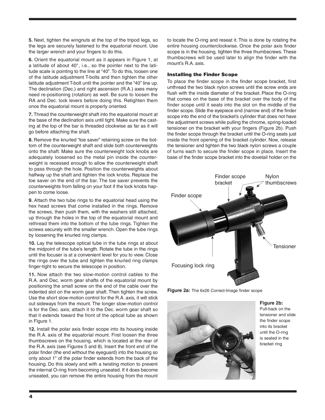
To place the finder scope in the finder scope bracket, first unthread the two black nylon screws until the screw ends are flush with the inside diameter of the bracket. Place the
Finder scope | Nylon |
bracket | thumbscrews |
Finder scope
Tensioner
Focusing lock ring
Figure 2a: The 6x26 Correct-Image finder scope
Figure 2b:
Pull‑back on the tensioner and slide the finder scope into its bracket until the O-ring
is seated in the bracket ring
4
