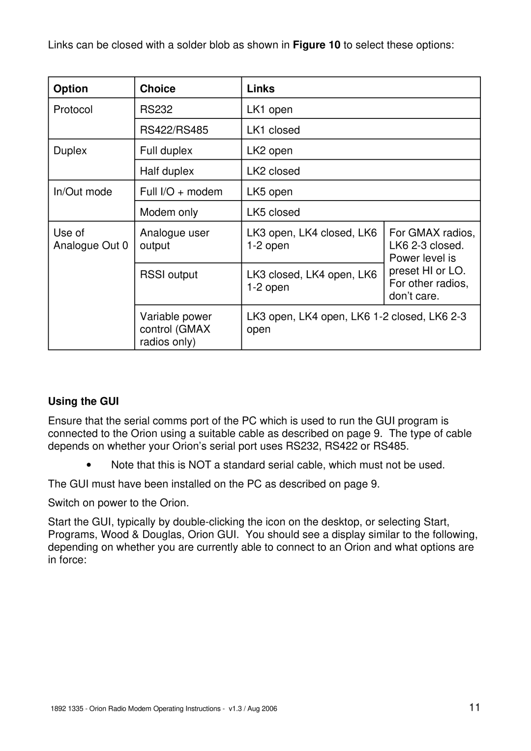
Links can be closed with a solder blob as shown in Figure 10 to select these options:
Option | Choice | Links |
|
|
|
|
|
Protocol | RS232 | LK1 open |
|
|
|
|
|
| RS422/RS485 | LK1 closed |
|
|
|
|
|
Duplex | Full duplex | LK2 open |
|
|
|
|
|
| Half duplex | LK2 closed |
|
|
|
|
|
In/Out mode | Full I/O + modem | LK5 open |
|
|
|
|
|
| Modem only | LK5 closed |
|
|
|
|
|
Use of | Analogue user | LK3 open, LK4 closed, LK6 | For GMAX radios, |
Analogue Out 0 | output | LK6 | |
|
|
| Power level is |
| RSSI output | LK3 closed, LK4 open, LK6 | preset HI or LO. |
| For other radios, | ||
|
| ||
|
| don’t care. | |
|
|
| |
|
|
|
|
| Variable power | LK3 open, LK4 open, LK6 | |
| control (GMAX | open |
|
| radios only) |
|
|
|
|
|
|
Using the GUI
Ensure that the serial comms port of the PC which is used to run the GUI program is connected to the Orion using a suitable cable as described on page 9. The type of cable depends on whether your Orion’s serial port uses RS232, RS422 or RS485.
vNote that this is NOT a standard serial cable, which must not be used. The GUI must have been installed on the PC as described on page 9.
Switch on power to the Orion.
Start the GUI, typically by
1892 1335 - Orion Radio Modem Operating Instructions - v1.3 / Aug 2006 | 11 |
