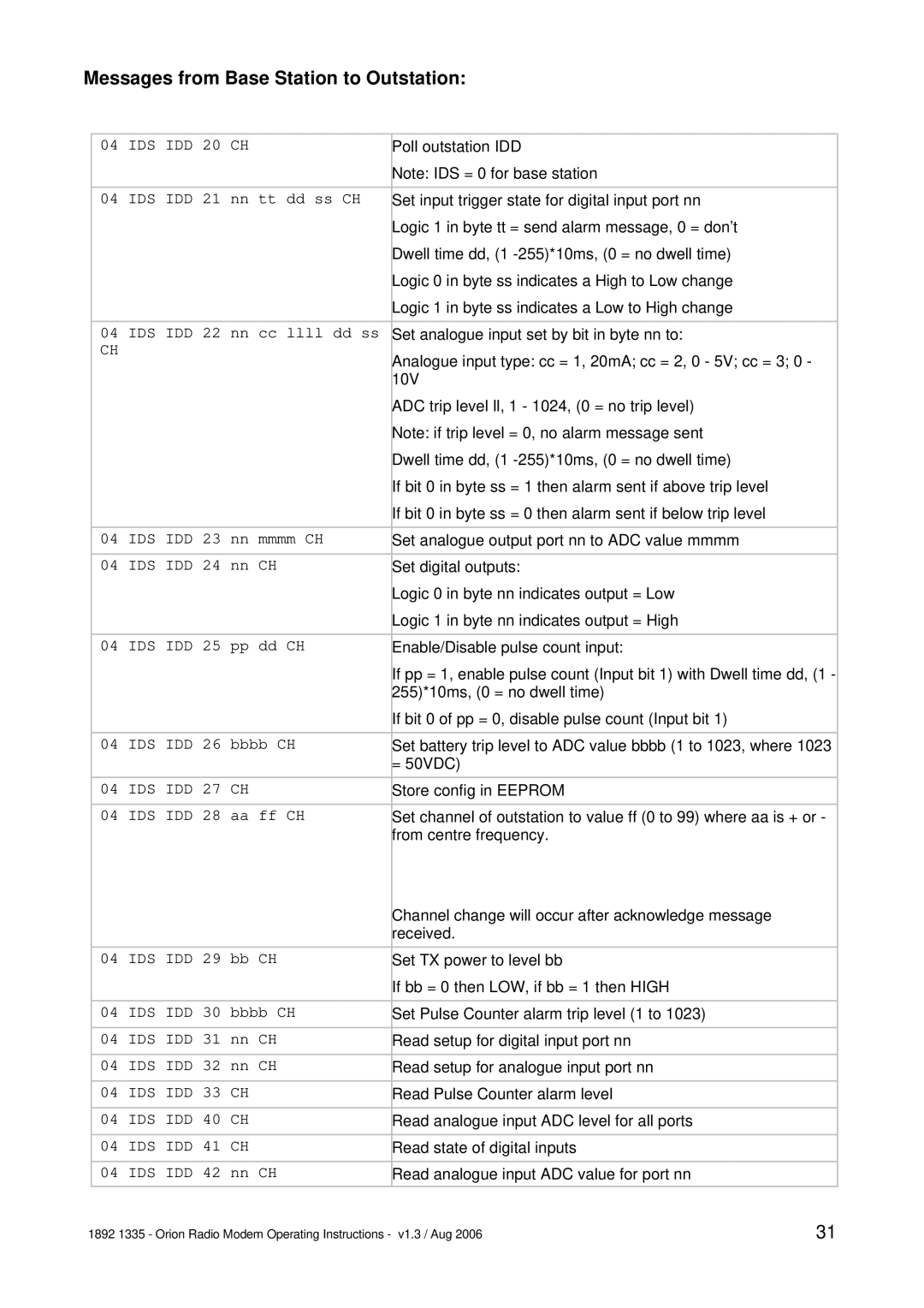
Messages from Base Station to Outstation:
04 | IDS IDD 20 CH | Poll outstation IDD |
|
| Note: IDS = 0 for base station |
|
|
|
04 | IDS IDD 21 nn tt dd ss CH | Set input trigger state for digital input port nn |
|
| Logic 1 in byte tt = send alarm message, 0 = don’t |
|
| Dwell time dd, (1 |
|
| Logic 0 in byte ss indicates a High to Low change |
|
| Logic 1 in byte ss indicates a Low to High change |
|
|
|
04 | IDS IDD 22 nn cc llll dd ss | Set analogue input set by bit in byte nn to: |
CH |
| Analogue input type: cc = 1, 20mA; cc = 2, 0 - 5V; cc = 3; 0 - |
|
| |
|
| 10V |
|
| ADC trip level ll, 1 - 1024, (0 = no trip level) |
|
| Note: if trip level = 0, no alarm message sent |
|
| Dwell time dd, (1 |
|
| If bit 0 in byte ss = 1 then alarm sent if above trip level |
|
| If bit 0 in byte ss = 0 then alarm sent if below trip level |
|
|
|
04 | IDS IDD 23 nn mmmm CH | Set analogue output port nn to ADC value mmmm |
|
|
|
04 | IDS IDD 24 nn CH | Set digital outputs: |
|
| Logic 0 in byte nn indicates output = Low |
|
| Logic 1 in byte nn indicates output = High |
|
|
|
04 | IDS IDD 25 pp dd CH | Enable/Disable pulse count input: |
|
| If pp = 1, enable pulse count (Input bit 1) with Dwell time dd, (1 - |
|
| 255)*10ms, (0 = no dwell time) |
|
| If bit 0 of pp = 0, disable pulse count (Input bit 1) |
|
|
|
04 | IDS IDD 26 bbbb CH | Set battery trip level to ADC value bbbb (1 to 1023, where 1023 |
|
| = 50VDC) |
|
|
|
04 | IDS IDD 27 CH | Store config in EEPROM |
|
|
|
04 | IDS IDD 28 aa ff CH | Set channel of outstation to value ff (0 to 99) where aa is + or - |
|
| from centre frequency. |
|
| Channel change will occur after acknowledge message |
|
| received. |
|
|
|
04 | IDS IDD 29 bb CH | Set TX power to level bb |
|
| If bb = 0 then LOW, if bb = 1 then HIGH |
|
|
|
04 | IDS IDD 30 bbbb CH | Set Pulse Counter alarm trip level (1 to 1023) |
|
|
|
04 | IDS IDD 31 nn CH | Read setup for digital input port nn |
|
|
|
04 | IDS IDD 32 nn CH | Read setup for analogue input port nn |
|
|
|
04 | IDS IDD 33 CH | Read Pulse Counter alarm level |
|
|
|
04 | IDS IDD 40 CH | Read analogue input ADC level for all ports |
|
|
|
04 | IDS IDD 41 CH | Read state of digital inputs |
|
|
|
04 | IDS IDD 42 nn CH | Read analogue input ADC value for port nn |
|
|
|
1892 1335 - Orion Radio Modem Operating Instructions - v1.3 / Aug 2006 | 31 |
