INSTRUCTIONS FOR PANAMAX SIGNAL LINE PROTECTION MODULES - PREMIUM SERIES
|
|
| Pull | LINE |
| EQUIP |
|
|
|
|
| Pull | LINE |
| EQUIP |
|
|
|
|
|
|
|
|
|
|
|
| ||||||
PullOut |
|
| IN | OUT |
| PullOut |
|
|
| IN | OUT |
| ||||
| Out | IN | OUT |
|
|
| Out |
|
| |||||||
|
|
|
| LINE |
| EQUIP | EQUIP |
|
|
|
|
| LINE |
| EQUIP | EQUIP |
|
|
| LINE | IN |
| OUT |
| LINE |
| EQUIP | LINE | IN |
| OUT | OUT | |
|
|
| IN |
| OUT |
| IN |
| OUT | IN |
| S110D | ||||
|
|
| S110D |
|
|
| S110D |
| S110D |
| S110D | S110D |
|
|
|
|
| LINE |
| EQUIP | LINE |
| EQUIP |
|
|
|
|
|
| LINE |
| EQUIP |
|
|
| IN |
| OUT |
|
|
|
|
|
| IN |
| OUT |
| ||
| IN |
| OUT |
|
|
|
|
|
|
|
|
| ||||
|
|
|
| LINE |
| EQUIP |
|
|
|
|
|
| LINE |
| EQUIP |
|
|
|
|
|
|
|
|
|
|
|
|
| IN |
| OUT |
| |
|
|
|
|
|
|
|
|
|
|
|
|
|
|
| |||||
|
|
| LINE | 1 | 1 |
|
|
| IN | ||
|
| SAT / | 2 | 2 | |
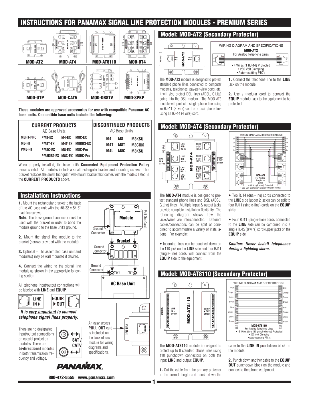
Model: MOD-AT2 (Secondary Protector)
|
|
|
| WIRING DIAGRAM AND SPECIFICATIONS |
|
|
|
|
| ||
PullOut |
| 1 - 8 | For Analog Telephone Lines | 1 - 8 | |
LINE | • 4 Wires (1 | ||||
|
| EQUIP |
|
| |
| IN |
| OUT |
|
|
|
|
|
| • 260 Volt Clamping |
|
|
|
|
| • |
|
|
|
|
|
|
| CATV | MODDBSTV- | EQUIP |
| 3 | OUTSIDE LINES | MODSPKP- | RECEIVER | 3 |
|
|
|
|
|
| OUT | Pull Out | |||||||
|
|
|
|
| 4 | 4 | ||||||||
Pull Out |
|
| Pull Out |
|
| 5 | 5 | |||||||
LINE | EQUIP. | SAT / | SAT / | 6 | 6 | |||||||||
IN | OUT | 7 | 7 | |||||||||||
|
| CATV | CATV | |||||||||||
|
| tuullPO rdCa |
| 8 | 8 | |||||||||
|
|
|
|
|
| |||||||||
These modules are approved accessories for use with compatible Panamax AC base units. Compatible base units include the following:
The
1.Connect the telephone line to the LINE jack on the module.
2.Use a modular cord to connect the EQUIP modular jack to the equipment to be protected.
CURRENT PRODUCTS | DISCONTINUED PRODUCTS |
AC Base Units | AC Base Units |
|
Model: MOD-AT4 (Secondary Protector)
WIRING DIAGRAM AND SPECIFICATIONS
|
| M4 | M8 | M8KSU | ||
M4T | M8T | M8COM | ||||
M4L | M8C | M8KSU | ||||
|
|
|
|
|
|
|
When properly installed, the base unit’s Connected Equipment Protection Policy remains valid. All modules include a small rectangular bracket and mounting screws. This bracket replaces the small triangular
Pull | LINE |
| EQUIP |
| |
IN |
| OUT |
| ||
Out |
|
| |||
|
|
| |||
| LINE | EQUIP | EQUIP | ||
LINE | IN | OUT | |||
OUT | |||||
IN | MOD | S110D | |||
S110D | IN | OUT | |||
|
|
|
| ||
| LINE |
| EQUIP |
| |
|
|
| |||
| LINE |
| EQUIP |
| |
| IN |
| OUT |
| |
|
|
|
Bl
Or
Gr
Br
1 - 81 - 4 1 - 4 1 - 4
• 260
![]()
![]() For Analog Telephone Lines
For Analog Telephone Lines ![]()
![]() • 4 Pairs (8 wires) Protected Volt Clamping •
• 4 Pairs (8 wires) Protected Volt Clamping •
Bl
Or
Gr
Br
1 - 4 1 - 4 1 - 4 1 - 8
Installation Instructions
1. Mount the rectangular bracket to the back |
of the AC base unit with the |
machine screws. |
Note: The brass ground connector must be |
used with the bracket in order to bond the |
module ground to the base unit’s ground. |
2. Mount the signal line module to the |
bracket (screws provided with the module). |
3. Optional – The assembled base unit and |
module(s) may be wall mounted if desired. |
4. Connect the wiring to the signal line |
module as shown in the appropriate follow- |
Module | PullOut |
Ground | Card |
| |
Connector |
|
Bracket |
|
Ground |
|
Connector |
|
Ground |
|
Connector |
|
The
•Incoming lines can be
EQUIP side to the equipment.
•Two RJ14
•Four RJ11
Caution: Never install telephones during a lightning storm.
ing section. |
Model: MOD-AT8110 (Secondary Protector)
All telephone input/output connections will be labeled with LINE and EQUIP.
| LINE |
| EQUIP. |
|
|
|
|
|
| ||
| IN |
| OUT |
|
|
|
|
|
|
|
|
|
|
|
|
|
|
It is very important to connect telephone signal lines properly.
There are no designated |
| |
input/output connections |
| |
on coaxial protection | SAT / | |
modules. These are | CATV | |
| ||
in both transmission fre- |
| |
quency and voltage. |
|
AC Base Unit |
An easy access | Pull | L | |
PULL OUT card | |||
| |||
Out | I | ||
is included on | |||
| |||
the back of each |
|
| |
module for wiring |
|
| |
diagrams and |
|
| |
specifications. |
|
|
PullOut | LINE | EQUIP | |
| IN |
| OUT |
| S110D |
| S110D |
The
WIRING DIAGRAM AND SPECIFICATIONS
Blue |
|
|
|
|
| Blue |
Orange |
|
|
|
|
| Orange |
|
|
|
|
| ||
Green |
|
|
|
|
| Green |
|
|
|
|
| ||
Brown |
|
|
|
|
| Brown |
|
|
|
|
| ||
Blue |
|
|
|
|
| Blue |
|
|
|
|
| ||
Orange |
|
|
|
|
| Orange |
|
|
|
|
| ||
Green |
|
|
|
|
| Green |
|
|
|
|
| ||
Brown |
|
|
|
|
| Brown |
|
|
|
|
| ||
110 |
| 110 |
| |||
| IDC | For Analog Telephone Lines | IDC | |||
•16 Wires (two 110
•260 Volt Clamping
•
cable to the LINE IN punchdown block on the module.
2. Punch down another cable to the EQUIP |
OUT punchdown block on the module and |
1.Cut the cable from the primary protector to the correct length and punch down the
connect to the phone equipment. |
1