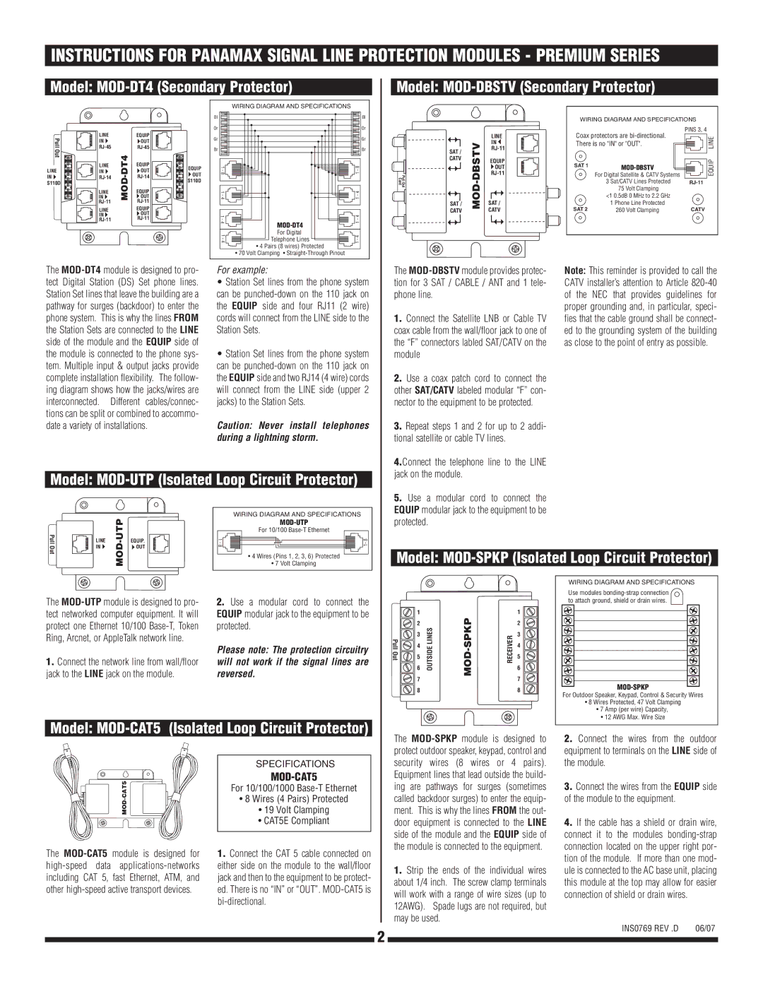
INSTRUCTIONS FOR PANAMAX SIGNAL LINE PROTECTION MODULES - PREMIUM SERIES
Model:
Model:
Pull | LINE |
| EQUIP |
| |
IN |
| OUT |
| ||
Out |
|
| |||
|
|
|
| ||
| LINE | EQUIP | EQUIP | ||
LINE | IN | OUT | |||
OUT | |||||
IN | MOD | S110D | |||
S110D | IN | OUT | |||
|
|
| |||
|
|
|
| ||
| LINE |
| EQUIP |
| |
|
|
| |||
| LINE |
| EQUIP |
| |
| IN |
| OUT |
| |
|
|
|
WIRING DIAGRAM AND SPECIFICATIONS
Bl |
| Bl |
Or |
| Or |
Gr |
| Gr |
Br |
| Br |
1 - 8 |
| 1 - 8 |
1 - 4 |
| 1 - 4 |
1 - 4 | 1 - 4 | |
|
| |
1 - 4 | For Digital | 1 - 4 |
Telephone Lines |
•4 Pairs (8 wires) Protected
•70 Volt Clamping •
Pull Out Card
SAT /
CATV
SAT /
CATV
MOD-DBSTV
LINE
IN ![]()
EQUIP ![]() OUT
OUT
SAT /
CATV
WIRING DIAGRAM AND SPECIFICATIONS
Coax protectors are | PINS 3, 4 | |||
|
| LINE | ||
There is no "IN" or "OUT". |
|
| ||
|
| EQUIP | ||
|
| |||
|
| |||
SAT 1 |
|
|
| |
|
|
| ||
|
|
|
| |
|
|
|
| |
| For Digital Satellite & CATV Systems |
|
|
|
| 3 Sat/CATV Lines Protected |
| ||
| 75 Volt Clamping |
|
|
|
| <1 0.5dB 0 MHz to 2.2 GHz |
|
|
|
SAT 2 | 1 Phone Line Protected |
| CATV | |
260 Volt Clamping |
| |||
The
For example:
•Station Set lines from the phone system can be
•Station Set lines from the phone system can be
Caution: Never install telephones during a lightning storm.
The
1.Connect the Satellite LNB or Cable TV coax cable from the wall/floor jack to one of the “F” connectors labled SAT/CATV on the module
2.Use a coax patch cord to connect the other SAT/CATV labeled modular “F” con- nector to the equipment to be protected.
3.Repeat steps 1 and 2 for up to 2 addi- tional satellite or cable TV lines.
Note: This reminder is provided to call the CATV installer’s attention to Article
Model: MOD-UTP (Isolated Loop Circuit Protector)
|
|
|
|
| WIRING DIAGRAM AND SPECIFICATIONS |
|
|
|
|
|
| ||
PullOut |
|
| For 10/100 | |||
LINE | EQUIP. | • 7 Volt Clamping | ||||
| IN |
| OUT |
|
|
|
|
|
|
|
| • 4 Wires (Pins 1, 2, 3, 6) Protected |
|
4.Connect the telephone line to the LINE jack on the module.
5.Use a modular cord to connect the EQUIP modular jack to the equipment to be protected.
Model: MOD-SPKP (Isolated Loop Circuit Protector)
The | 2. Use a modular cord to connect the | |
tect networked computer equipment. It will | EQUIP modular jack to the equipment to be | |
protect one Ethernet 10/100 | protected. | |
Ring, Arcnet, or AppleTalk network line. | Please note: The protection circuitry | |
1. Connect the network line from wall/floor | ||
will not work if the signal lines are | ||
jack to the LINE jack on the module. | reversed. |
Model: MOD-CAT5 (Isolated Loop Circuit Protector)
Pull Out
1 |
| |
2 | LINES | |
3 | ||
| ||
4 | OUTSIDE | |
6 | ||
5 |
|
7
8
MOD-SPKP
RECEIVER
1
2
3
4
5
6
7
8
WIRING DIAGRAM AND SPECIFICATIONS |
Use modules |
to attach ground, shield or drain wires. |
|
For Outdoor Speaker, Keypad, Control & Security Wires |
• 8 Wires Protected, 47 Volt Clamping |
• 7 Amp (per wire) Capacity, |
• 12 AWG Max. Wire Size |
|
| SPECIFICATIONS |
PullOut | ||
• 19 Volt Clamping | ||
|
| For 10/100/1000 |
|
| • 8 Wires (4 Pairs) Protected |
|
| • CAT5E Compliant |
The | 1. Connect the CAT 5 cable connected on | |
either side on the module to the wall/floor | ||
including CAT 5, fast Ethernet, ATM, and | jack and then to the equipment to be protect- | |
other | ed. There is no “IN” or “OUT”. | |
|
|
|
The
1.Strip the ends of the individual wires about 1/4 inch. The screw clamp terminals will work with a range of wire sizes (up to 12AWG). Spade lugs are not required, but may be used.
2.Connect the wires from the outdoor equipment to terminals on the LINE side of the module.
3.Connect the wires from the EQUIP side of the module to the equipment.
4.If the cable has a shield or drain wire, connect it to the modules
|
| INS0769 REV .D | 06/07 | |
2 | ||||
|
|
| ||
|
|
| ||
|
|
|
|