Electrical Connections (continued)
(Only for CQ-5300U)
Cautions:
![]() This product is designed to operate with a
This product is designed to operate with a
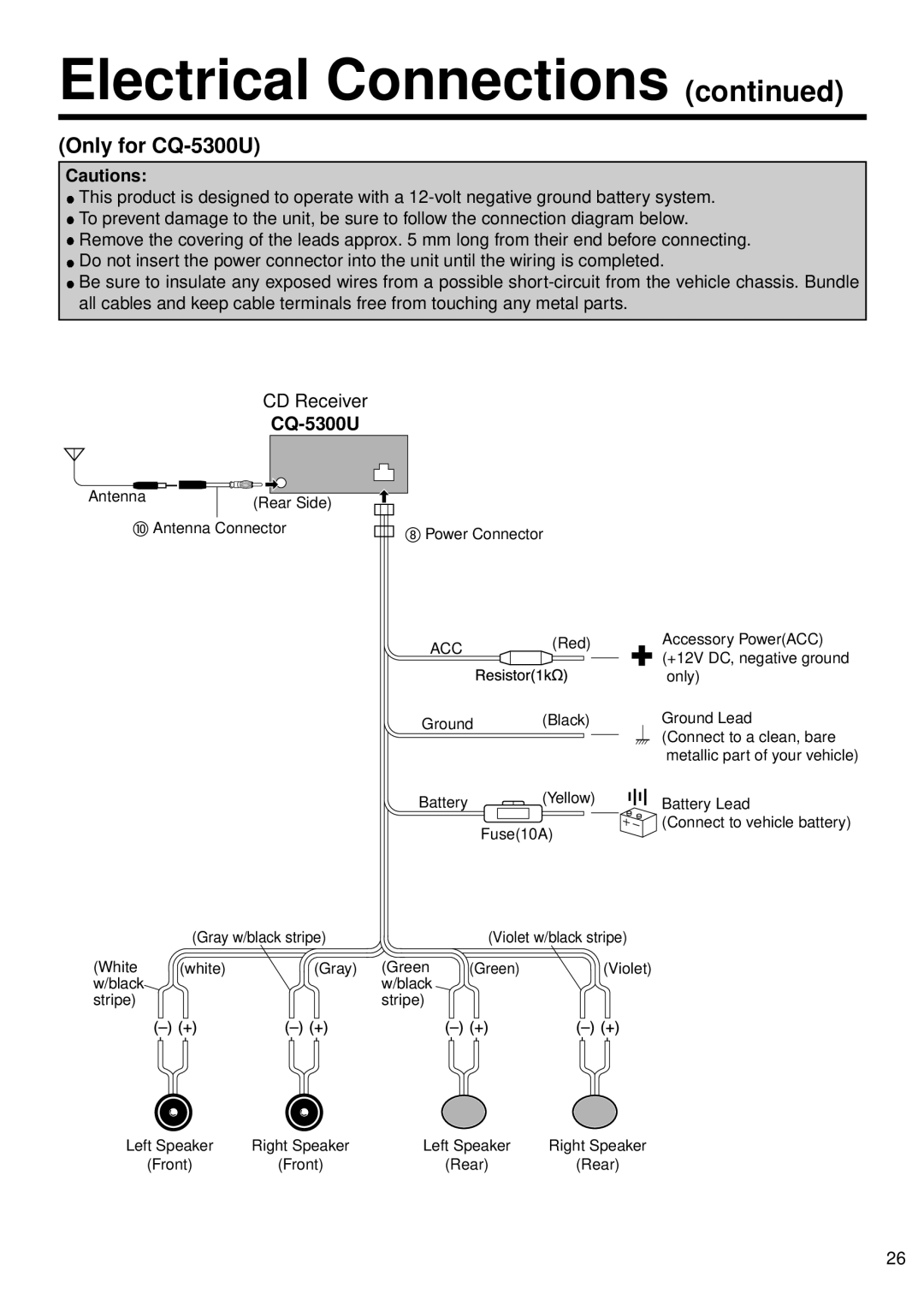
![]() To prevent damage to the unit, be sure to follow the connection diagram below.
To prevent damage to the unit, be sure to follow the connection diagram below.
![]() Remove the covering of the leads approx. 5 mm long from their end before connecting.
Remove the covering of the leads approx. 5 mm long from their end before connecting.
![]() Do not insert the power connector into the unit until the wiring is completed.
Do not insert the power connector into the unit until the wiring is completed.
![]() Be sure to insulate any exposed wires from a possible
Be sure to insulate any exposed wires from a possible
CD Receiver
CQ-5300U
Antenna |
|
|
|
|
|
|
|
|
|
|
|
|
|
| |
|
|
|
|
|
|
| |
|
|
|
|
| (Rear Side) | ||
|
|
|
|
|
| ||
|
|
| |||||
| Antenna Connector | ||||||
| (Gray w/black stripe) | |
(White | (white) | (Gray) |
w/black |
|
|
stripe) |
|
|
Power Connector
ACC(Red)
Ground (Black)
Battery ![]() (Yellow)
(Yellow)
Fuse(10A)
| (Violet w/black stripe) | |
(Green | (Green) | (Violet) |
w/black |
|
|
stripe) |
|
|
Accessory Power(ACC) (+12V DC, negative ground only)
Ground Lead
(Connect to a clean, bare metallic part of your vehicle)
Battery Lead
(Connect to vehicle battery)
Left Speaker | Right Speaker | Left Speaker | Right Speaker |
(Front) | (Front) | (Rear) | (Rear) |
26
