
CQ-DP153W specifications
The Panasonic CQ-DP153W is a versatile and feature-rich car stereo designed to enhance your in-car audio experience. As a part of Panasonic's commitment to delivering high-quality audio systems, the CQ-DP153W showcases a range of technologies that cater to music enthusiasts and casual listeners alike.One of the standout features of the CQ-DP153W is its ability to play a wide variety of audio formats. It supports CD, CD-R, and CD-RW playback, as well as MP3 and WMA files, providing flexibility in how you enjoy your music. This versatility is further enhanced by its built-in radio tuner, which allows users to access AM and FM stations with ease. The unit also typically includes features like 30 station presets, ensuring that your favorite channels are always just a button away.
The CQ-DP153W is equipped with a user-friendly interface, including an easy-to-read LCD display that provides clear visibility of track information, radio frequencies, and settings. The control layout is intuitive, allowing drivers to navigate through their music selections and settings without distractions, ensuring both safety and convenience while on the road.
Sound quality is paramount in the design of the CQ-DP153W. The stereo features a robust equalizer with multiple preset sound modes, enabling users to customize their audio experience to their personal taste. Additionally, it incorporates advanced audio technologies such as bass enhancement and loudness control, further improving sound output and clarity.
Another noteworthy aspect of the CQ-DP153W is its connectivity options. While it may not possess the advanced Bluetooth capabilities of modern car stereos, it typically includes an auxiliary input, allowing you to connect external devices like smartphones and portable music players directly. This feature broadens the options for audio playback, making it easier to enjoy your favorite playlists from various sources.
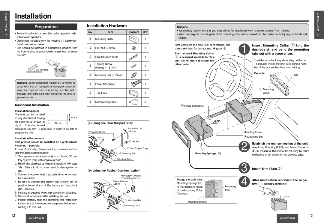
Durability and ease of installation are also important characteristics of the CQ-DP153W. Designed to fit standard car stereo slots, it comes with a robust build that can withstand the rigors of everyday use in a vehicle.
Overall, the Panasonic CQ-DP153W represents a solid choice for anyone looking to upgrade their car audio system. With its blend of versatility, durability, and user-friendly features, this car stereo is sure to provide a satisfying listening experience on the go.