ENGLISH |
OPTIONAL EQUIPMENT CONNECTIONS |
|
|
|
|
|
|
| ||||
Optional Equipment Connections |
|
|
|
|
|
|
| ||||
Note: The remote control must be programmed with supplied | connected to the video inputs. See the optional equipment | ||||||||||
codes to operate the optional equipment. |
| manual for details |
|
|
|
| |||||
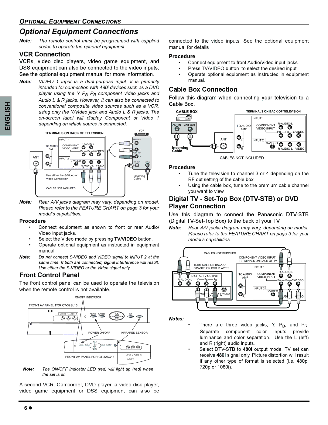
VCR Connection |
|
| Procedure |
|
|
|
| ||||
VCRs, video disc players, video game equipment, and | • Connect equipment to front Audio/Video input jacks. | ||||||||||
DSS equipment can also be connected to the video inputs. | • | Press TV/VIDEO button | to select the desired input. | ||||||||
See the optional equipment manual for more information. | • Operate optional equipment as instructed in equipment | ||||||||||
Note: VIDEO 1 input is a |
| manual. |
|
|
|
| |||||
intended for connection with 480i devices such as a DVD | Cable Box Connection |
|
|
| |||||||
player using the Y PB PR component video jacks and |
|
|
| ||||||||
Follow this diagram when connecting your television to a | |||||||||||
Audio L & R jacks. However, it can also be connected to | |||||||||||
Cable Box. |
|
|
|
| |||||||
conventional composite video sources such as a VCR, |
|
|
|
| |||||||
CABLE BOX |
|
|
|
| |||||||
using only the Y/Video jack and Audio L & R jacks. The |
| TERMINALS ON BACK OF TELEVISION | |||||||||
| 15 |
|
| INPUT 1 |
| ||||||
depending on which source is connected. |
| ANT IN | ANT OUT | TO AUDIO | COMPONENT | ||||||
|
|
| VCR |
|
|
|
| AMP | VIDEO INPUT |
| |
|
|
|
|
|
|
|
| PR | PB Y/VIDEO | ||
| TERMINALS ON BACK OF TELEVISION |
|
|
|
|
| |||||
|
| INPUT 1 | VIDEO OUT |
|
|
| ANT | L | INPUT 2 |
| |
|
| COMPONENT |
|
|
|
|
|
| |||
| TO AUDIO |
|
| Incoming |
| R | |||||
| AMP | VIDEO INPUT | L |
|
| ||||||
|
| PR PB Y/VIDEO |
| Cable |
|
|
|
|
| ||
|
|
| AUDIO OUT |
|
|
|
|
|
|
| |
ANT |
|
| R |
|
|
| CABLES NOT INCLUDED |
| |||
L | INPUT 2 |
|
|
|
|
| |||||
|
| ANT OUT | ANT IN | Procedure |
|
|
|
| |||
| R |
|
|
|
|
|
| ||||
|
|
| Use either the |
|
|
|
|
|
|
|
|
|
|
|
|
| • Tune the television to channel 3 or 4 depending on the | |
|
|
|
|
|
|
|
|
|
|
|
|
|
|
|
| |||
|
|
|
|
|
|
|
|
|
|
|
|
|
|
| Incoming |
| RF out setting of the cable box. | |
|
|
| Video Connection |
|
|
|
|
|
|
|
|
|
| Cable |
| |||
|
|
| CABLES NOT INCLUDED |
|
|
|
|
|
|
| • Using the cable box, tune to the premium cable channel | |||||||
|
|
|
|
|
|
|
|
|
| |||||||||
|
|
|
|
|
|
|
|
|
| you want to view. | ||||||||
|
|
|
|
|
|
|
|
|
|
|
|
|
|
|
|
| ||
|
|
|
|
|
|
|
|
|
|
|
|
|
|
|
|
| ||
Note: Rear A/V jacks diagram may vary, depending on model. | Digital TV - | |||||||||||||||||
Player Connection | ||||||||||||||||||
|
|
| Please refer to the FEATURE CHART on page 3 for your | |||||||||||||||
|
|
| model’s capabilities. |
|
|
|
|
|
|
| Use this diagram to connect the Panasonic | |||||||
Procedure |
|
|
|
|
|
|
| (Digital | ||||||||||
• Connect equipment | as shown to front or rear Audio/ | Note: Rear A/V jacks diagram may vary, depending on model. | |||||||||||
| Video input jacks. |
|
|
| Please refer to the FEATURE CHART on page 3 for your | ||||||||
• Select the Video mode by pressing TV/VIDEO button. | model’s capabilities. |
|
|
|
|
| |||||||
• Operate optional equipment as instructed in equipment |
|
|
|
|
|
|
|
|
| ||||
| manual. |
|
|
|
|
| CABLES NOT SUPPLIED |
|
|
|
|
| |
Note: | Do not connect |
|
|
|
|
|
|
| |||||
|
|
|
| COMPONENT VIDEO INPUT |
|
|
| ||||||
| same time. If both are connected, signal interference will result. |
|
|
|
| TERMINALS ON BACK OF TV |
|
|
| ||||
|
| TERMINALS ON BACK OF |
|
|
|
|
| ||||||
| Use either the |
|
| INPUT 1 |
|
|
| ||||||
|
|
|
|
|
| ||||||||
|
|
|
|
|
|
|
|
|
|
|
|
| |
Front Control Panel |
|
|
|
|
|
|
| AMP | VIDEO INPUT | ||||
|
|
|
|
| DIGITAL TV OUTPUT | TO AUDIO | COMPONENT |
|
|
| |||
|
|
|
|
|
|
|
|
|
| ||||
The front control panel can be used to operate the television | Y | PB | PR |
|
| PR | PB | Y/VIDEO | |||||
|
|
|
|
|
|
| |||||||
when the remote control is not available. |
|
|
|
|
|
| L |
|
| ||||
|
|
|
|
|
|
|
|
| INPUT 2 |
|
|
| |
|
|
|
|
|
|
| AUDIO | R |
|
| AUDIO | ||
| ON/OFF INDICATOR |
|
|
|
|
|
|
|
| ||||
|
|
|
|
|
|
|
|
|
|
|
| ||
FRONT AV PANEL FOR |
|
|
|
|
|
|
|
|
|
|
|
| |
| VIDEO 3 L - AUDIO - R | POWER TV/VIDEO | CH | EXIT |
|
|
|
|
|
|
|
|
|
| ACTION | Notes: |
|
|
|
|
|
|
|
| |||
|
| VOL |
| VOL |
|
|
|
|
|
|
|
| |
|
|
| CH |
|
|
|
|
|
|
|
|
| |
|
|
|
|
| • |
| There | are three | video | jacks, Y, | PB, | and PR. | |
|
|
|
| POWER ON/OFF | INFRARED SENSOR | Separate component color inputs provide |
|
|
|
| |||
|
|
|
|
|
| luminance and color separation. Use the L (left) |
|
|
|
| ACTION |
| and R (right) audio inputs. |
|
|
|
| CH |
|
|
|
|
| POWER VOL | VOL TV / VIDEO | • | Select |
|
|
|
| CH | ||
|
|
|
| VIDEO L - AUDIO - R | receive 480i signal only. Picture distortion will result | |
|
| FRONT AV PANEL FOR | ||||
|
|
|
|
| INPUT 3 | if any other type of format is selected (i.e. 480p, |
Note: | The ON/OFF indicator LED (red) will light up (red) when | 720p or 1080i). | ||||
| ||||||
| the set is on. |
|
|
| ||
A second VCR, Camcorder, DVD player, a video disc player, video game equipment or DSS equipment can also be
6z