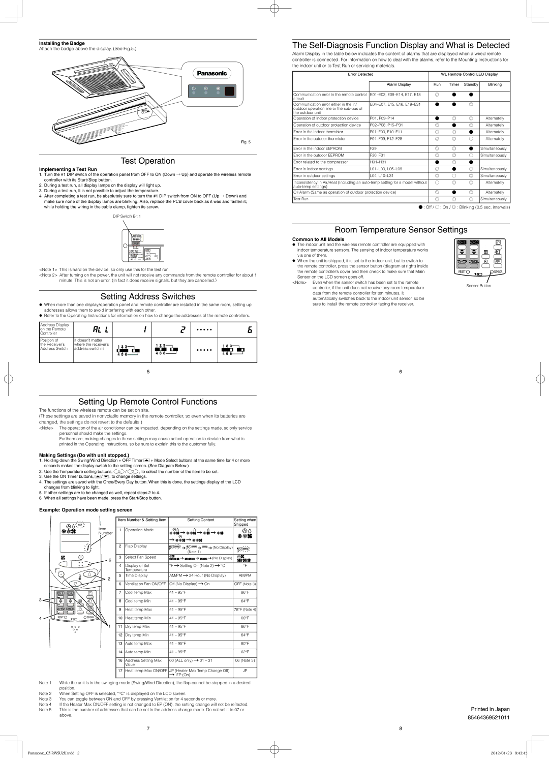
Installing the Badge
Attach the badge above the display. (See Fig.5.)
Fig. 5
Test Operation
Implementing a Test Run
1.Turn the #1 DIP switch of the operation panel from OFF to ON (Down → Up) and operate the wireless remote controller with its Start/Stop button.
2.During a test run, all display lamps on the display will light up.
3.During a test run, it is not possible to adjust the temperature.
4.After completing a test run, be absolutely sure to turn the #1 DIP switch from ON to OFF (Up → Down) and make sure none of the display lamps are blinking. Also, replace the PCB cover back as it was and fasten it; while holding the wiring in the cable clamp, tighten its screw.
DIP Switch Bit 1
<Note 1> This is hard on the device, so only use this for the test run.
<Note 2> After turning on the power, the unit will not receive any commands from the remote controller for about 1 minute. This is not an error. (In fact it does receive signals, but they are cancelled.)
Setting Address Switches
When more than one display/operation panel and remote controller are installed in the same room, setting up addresses allows them to avoid interfering with each other.
Refer to the Operating Instructions for information on how to change the addresses of the remote controllers.
Address Display | |
on the Remote | ・・・・・ |
Controller | |
Position of | It doesn’t matter | |
the Receiver’s | where the receiver’s | |
Address Switch | address switch is. | ・・・・・ |
| |
5
The Self-Diagnosis Function Display and What is Detected
Alarm Display in the table below indicates the content of alarms that are displayed when a wired remote controller is connected. For information on how to deal with the alarms, refer to the Mounting Instructions for the indoor unit or to Test Run or servicing materials.
Error Detected | | WL Remote Control LED Display |
| | | | | |
| Alarm Display | Run | Timer | Standby | Blinking |
| | | | | |
Communication error in the remote control | E01–E03, E08–E14, E17, E18 | ◎ | ● | ● | |
circuit | | | | | |
Communication error either in the in/ | E04–E07, E15, E16, E19–E31 | ● | ● | ◎ | |
outdoor operation line or the sub-bus of | | | | | |
the outdoor unit | | | | | |
Operation of indoor protection device | P01, P09–P14 | ● | ◎ | ◎ | Alternately |
| | | | | |
Operation of outdoor protection device | P02–P08, P15–P31 | ◎ | ● | ◎ | Alternately |
| | | | | |
Error in the indoor thermistor | F01–F03, F10–F11 | ◎ | ◎ | ● | Alternately |
| | | | | |
Error in the outdoor thermistor | F04–F09, F12–F28 | ◎ | ◎ | ○ | Alternately |
| | | | | |
Error in the indoor EEPROM | F29 | ◎ | ◎ | ● | Simultaneously |
| | | | | |
Error in the outdoor EEPROM | F30, F31 | ◎ | ◎ | ○ | Simultaneously |
| | | | | |
Error related to the compressor | H01–H31 | ● | ◎ | ● | |
| | | | | |
Error in indoor settings | L01–L03, L05–L09 | ◎ | ● | ◎ | Simultaneously |
| | | | | |
Error in outdoor settings | L04, L10–L31 | ◎ | ○ | ◎ | Simultaneously |
| | | | | |
Inconsistency in Air/Heat (Including an auto-temp setting for a model without | ○ | ◎ | ◎ | Alternately |
auto-temp settings) | | | | | |
Oil Alarm (Same as operation of outdoor protection device) | ◎ | ● | ◎ | Alternately |
| | | | | |
Test Run | | ◎ | ◎ | ◎ | Simultaneously |
| | | | | |
● : Off / ○ : On / ◎ : Blinking (0.5 sec. intervals)
Room Temperature Sensor Settings
| Common to All Models | |
| The indoor unit and the wireless remote controller are equipped with | |
| indoor temperature sensors. The sensing of indoor temperature works | |
| via one of them. | |
| When the unit is shipped, it is set to the indoor unit, but to switch to | |
| the remote controller, press the sensor button (diagram at right) inside | |
| the remote controller’s cover and then check to make sure that Main | |
| Sensor on the LCD screen goes off. | |
| <Note> Even when the sensor switch has been set to the remote | Sensor Button |
| controller, if the unit does not receive any room temperature |
| |
| data from the remote controller for ten minutes, it | |
automatically switches back to the indoor unit sensor, so be sure to install the remote controller facing the receiver.
6
Setting Up Remote Control Functions
The functions of the wireless remote can be set on site.
(These settings are saved in nonvolatile memory in the remote controller, so even when its batteries are changed, the settings do not revert to the defaults.)
<Note> The operation of the air conditioner can be impacted, depending on the settings made, so only service personnel should make the settings.
Furthermore, making changes to these settings may cause actual operation to deviate from what is printed in the Operating Instructions, so be sure to explain this to the customer fully.
Making Settings (Do with unit stopped.)
1.Holding down the Swing/Wind Direction + OFF Timer  + Mode Select buttons at the same time for 4 or more seconds makes the display switch to the setting screen. (See Diagram Below.)
2.Use the Temperature setting buttons,  /
/  , to select the number of the item to be set.
3.Use the ON Timer buttons,  /
/  , to change settings.
4.The settings are saved with the Once/Every Day button. When this is done, the settings display of the LCD changes from blinking to light.
5.If other settings are to be changed as well, repeat steps 2 to 4.
6.When all settings have been made, press the Start/Stop button.
Example: Operation mode setting screen
Note 1 While the unit is in the swinging mode (Swing/Wind Direction), the fl ap cannot be stopped in a desired position.
Note 2 When Setting OFF is selected, “°C” is displayed on the LCD screen.
Note 3 You can toggle between ON and OFF by pressing Ventilation for 4 seconds or more.
Note 4 If the Heater Max ON/OFF setting is not changed to EP (ON), the setting change will not be refl ected. Note 5 This is the number of addresses that can be set in the address change mode. Do not set it to 07 or
above.
Printed in Japan
85464369521011